A page for ‘how stuff works’. Feel free to use (being credited would be nice… will be adding content over time).

NEW ZEALAND RAILWAYS CORPORATION 30-CLASS (LATER ‘EF’) ELECTRIC LOCOMOTIVE
A ‘brief’ specification’ data sheet for the EF locomotives – NZR Class 30 SpecsDoc
LOCOMOTIVE CAB DESIGN
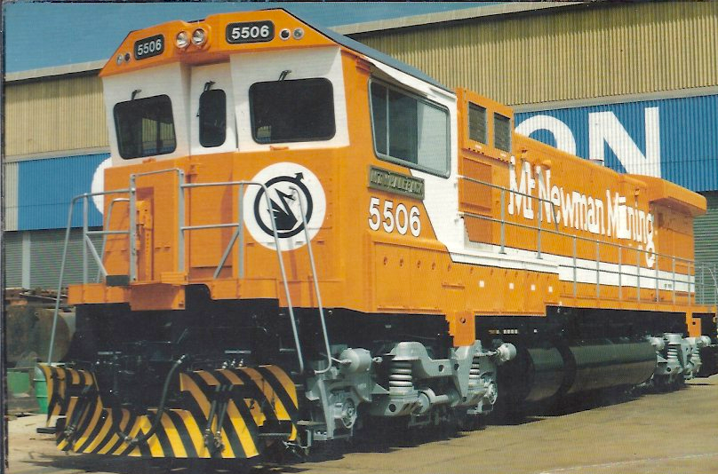
In 1981 I arrived in Port Hedland in the Pilbara region of the far north-west of Western Australia. I had resigned from my locomotive driver’s position with New Zealand Railways to take up a similar position on the iron ore railroad of the Mt. Newman Mining Co. Pty. Ltd. This company would later become BHP Billiton Iron Ore.
The craft union then representing Pilbara locomotive enginemen (there were no females among our cohort then) was the Federated Enginedriver’s & Fireman’s Union, a national union for enginedrivers and their assistants working (mostly) in stationary industrial service. This included those who operated and maintained the diesel engines and generators in the company and township power houses. Apparently, the national locomotive enginemen’s organisation—the Australian Federated Union of Locomotive Enginemen—was politically unable to assume coverage of mining company locomotive staff.
In New Zealand I had developed an interest in industrial ergonomics and the design of locomotive (and train) operator’s workspaces. I had been involved, in New Zealand, in a work-group within our craft union—the NZ Locomotive Engineer’s Association—known as the ‘Cab Committee’. This elected group represented all locomotive engineers on the NZR in aspects of the design of cabs and on-board workspaces on new motive power and other self-propelled rollingstock.
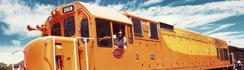
A couple of years after my arrival in Port Hedland it transpired that MNM desired to modernise its locomotive fleet by having its 3,600 hp early-1970s-era Alco Century Series diesel-electric locomotives ‘upgraded’ to something better and more powerful. An Australian heavy industry manufacturer, A. Goninan & Co. (who happened to be the Australian licensee for General Electric Transportation Systems in the USA), secured a contract from MNM to rebuild these units into modern GE Dash 7 units (actually, ‘Dash 7-and-a-half’, since the technology for Dash 7s had evolved somewhat since its introduction).
When I became aware of this I sought to have our drivers involved in the locomotive cab design phase of the project and took this proposal to a union meeting. Our workgroup already had a ‘cab committee’, but this had historically only been involved with maintenance of the interior conditions of current locomotive cabs, and providing input when items of equipment were to be added. I thought this rebuild project was a perfect opportunity for us to assume some responsibility for and involvement in ensuring that the rebuilt locomotives had cab conditions commensurate with modern ergonomic principles and the new North American Clean Cab standards. In other words, a cab layout that suited the requirements of those who would operate the locomotives.
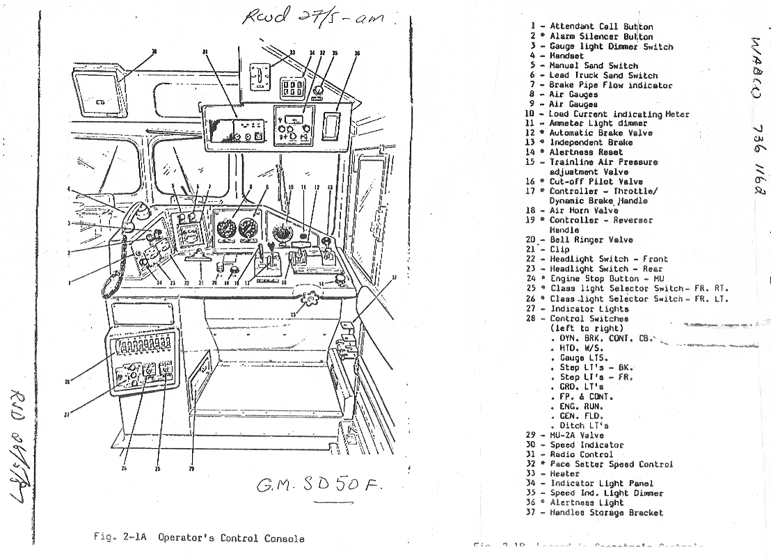
I subsequently brought a series of graphic proposals to the union as ‘starting point’ ideas for cab layout. I had seen the upgraded cab-style adopted by another Pilbara iron ore company—Hamersley Iron—and been impressed with some of its features. These included the standard of cab air conditioning, the control stand layout, equipment placement, cab access, solar protection, and overall cab shape.
Calling it their ‘Pilbara Cab’, Hamersley Iron had done away with the short-hood, adopted a reverse-angle front windscreen design that minimised sun glare and solar heat transfer, a cab front door arrangement intended to solve the problem of drafty doors in front of crew members, upgraded crew toilet facilities, a cab-side window design that didn’t rattle, and modern seating. In service, this design turned out to have some deficiencies and our group sought to use this experience to make certain modifications to our version.
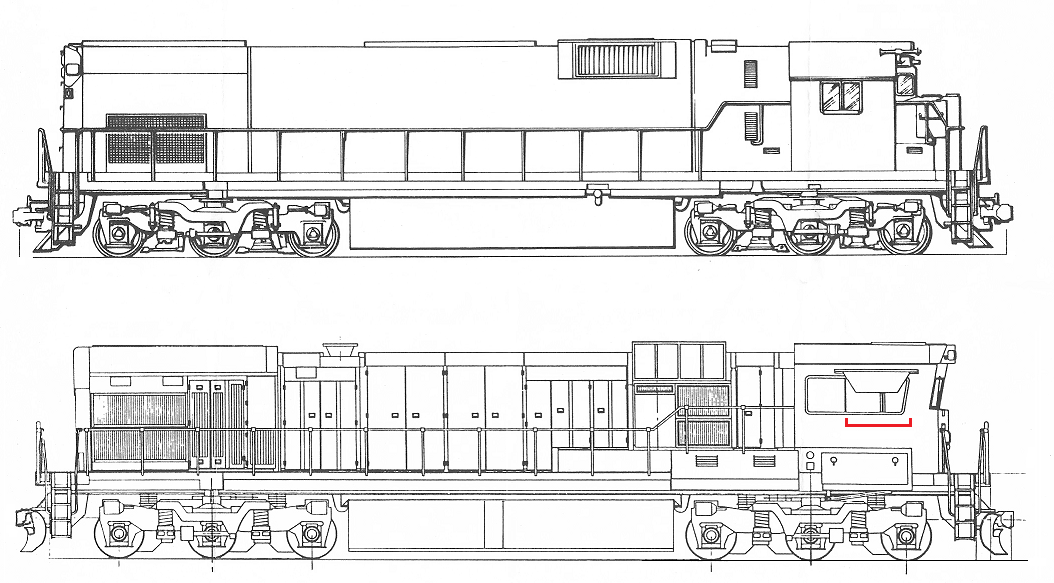
The following images depict our ‘cab-design’ journey. The concept drawings are mine, were supplied to the company, and were used by Goninan’s in the determination of cab layout and production of full-size cab mock-ups.
The committee were subsequently also involved in the cab design of the GE Dash 8 units that followed. The first four of these units were likewise built on recycled Alco under-frames and bogies, and were also fitted with the ‘Mt Newman’ version of the Pilbara Cab. All of these units—except one, retained for display in Port Hedland—have now been withdrawn and scrapped. In a new era, with a new generation of management personnel, the BHP Iron Ore railroad is nowadays an all-EMD operation.

Bringing some anthropometric discipline to the design – 1, with acknowledgment to NZR and Prof. Fred Gamst

Bringing some anthropometric discipline to the design – 2

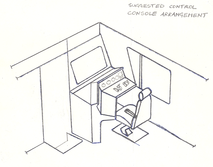
This proposal was an attempt to bring new air brake valve technology and a flat control desk arrangement into the cab. The concept suggested using the standard GE controller switch panel oriented horizontally. This idea was actually adopted, some years later, by Westrail in their P Class GE Dash 8s built by A. Goninan & Co.

Compare this concept drawing with photos of the eventual product. Note the 4-position headlight switches (Off, Low, Med, High). This idea resulted from a union request. Most of the railroad had a well-built and maintained gravel-surfaced access road running immediately parallel and it was used by public as well as company traffic. Since much of the railroad was along long tangent sections, locomotive drivers were obliged to dim their headlights at night for extended distances so as not to blind on-coming drivers. The ‘Medium’ position was a practical solution that helped both parties.

MORE ON LOCOMOTIVE CAB DESIGN
A graphic design proposal – CabDesign1 – Proposals for minimum cab standards on MNM locos
A graphic design proposal – CabDesign2 – Proposed cab standards: MNM locomotives – FEDFU submission
A graphic design proposal – CabDesign3 – Proposed cab layout: Goninan rebuilds – FEDFU submission
A 1977 British Institution of Mechanical Engineers paper – The Design of Driver’s Cabs
A console proposal not eventually adopted by MNM (but it did impress Westrail, and a similar layout appeared later in their new P-Class Dash 8s) – Suggested Control Console Arrangement: New Locomotive – FEDFU submission
A great academic paper – Prof. Fred Gamst: The Diesel-Electric Locomotive as a Work Environment – A study in applied anthropology
THE BAKER STEAM LOCOMOTIVE VALVE GEAR
The Baker valve gear was applied to one class of New Zealand Government Railways locomotives and—retrospectively—as a modification to two members of another class. Both of these locomotive classes—members of the J and K series sub-classes—were designed and entered service during the waning decades of steam locomotion that were also the zenith of design in the US. These modern NZR fleets were even allocated class designations that reflected some of the most successful locomotive classes then running on major eastern US railroads.
But these NZR locomotives didn’t just receive the class designations of some modern American locomotives; they were also equipped—variously—with modern steam locomotive appliances and design features. These included air-operated firedoors, multiple-valve front-end throttles, leading and trailing truck designs, boiler blow-down systems, roller-bearing siderods, Vanderbilt tenders, and—in the case of the J-classes (and two KAs)—Baker valve gear.
The Baker gear had become popular in the US on large, modern steam locomotives, so it is understandable that our mechanical engineering decision-makers might opt for it at this time (the 1940s and 50s). But Baker gear was successful in the US because it suited a certain type of locomotive, and such a locomotive was more likely to be a dedicated freight or passenger unit than the composite machines that NZR locomotives invariably had to be.
Perhaps the most significant feature of a steam locomotive especially intended for use with the Baker gear was the design of steam ports and passages that were optimised to gain from its subtle features. I have no idea if this specialisation to steamways was done (or able to be done) with the design of the J classes, but I do know that there have been some overstated advantages for the Js of having been equipped with Baker gear. Readers might like to decide for themselves…
Some notes on the Baker locomotive valve gear – The Baker Valve Gear For Steam Locomotives
A quick look at how it works. You might even understand it after reading this – A brief description of the Baker valve gear
Also, a manufacturer’s technical manual – Baker Valve Gear 1946
THE AMERICAN MULTIPLE-VALVE FRONT-END THROTTLE
Much explanatory material exists in both rail industry and railfan media that describes modern steam locomotives; including, sometimes, detail of their design and construction. It seems, though, that whereas feedwater heaters, tender design, trailing trucks, roller-bearing siderods, and even air-operated firedoors often rate some degree of description, the modern front-end throttle scarcely ever does. This has always bemused me, as this device is a classic and effective feature of modern American-style steam locomotives.
The New Zealand Government Railways applied the front-end throttle to two classes of locomotive; the C class 2-6-2 shunting locomotives of 1930 and the K class 4-8-4 of 1932 (and its variants). This exposé will focus on this type of steam locomotive throttle.
The steam locomotive throttle valve is designed to regulate the supply of steam to the cylinder valves and was able to be a simple device so long as boiler pressures remained low. This was the case during the first decades of the 19th century, and a simple, uncomplicated valve was found satisfactory for this function.
The early Stevenson locomotives—including those exported to the United States—were fitted with a primitive cock valve, which consisted of a hollow plug with a narrow slot aperture that opened or closed when rotated. This valve was mounted inside the boiler at the rear wrapper sheet of the backhead, was convenient to the footplate, and required no complex linkage; only a stuffing box for the valve stem and a throttle lever.
For all its simplicity though, this plug throttle was a crude and imprecise regulator and was abandoned by George Stevenson in about 1833 to be replaced by the butterfly valve. Following this, American manufacturers soon adopted the slide-throttle valve—looking much like the common D-shaped valve with two or three rectangular steam openings—and this became the standard American throttle valve prior to 1865.
Although the type of throttle valve was settled early, its placement changed frequently during the first 30 years. At first it was centred inside the boiler above the crown sheet, whereby a collecting pipe—extending vertically—gathered drier steam from the top of the boiler. By the mid-1840s though, throttle valves were being mounted atop the collecting pipe, and—beginning in the early 1850s—within the smokebox.
It has been reported that by 1860 nearly all American locomotives were equipped with throttle valves located in the smokebox (Figure 1). The chief advantage claimed for this position was that because the throttle valve was not inside the boiler it was more accessible for inspection and repair. The chief disadvantage was that the valve was prone to overheat and stick because of high smokebox temperatures. In the 1870s the poppet throttle valve was developed and this made these front-end throttles obsolescent until the idea was revived in the 1920s.
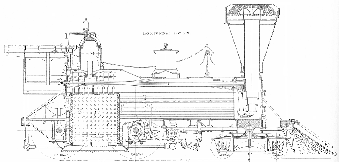
FIGURE 1: These sectional diagrams, from A History of The American Locomotive – Its development 1830-1880, of the 6-foot-gauge wood-burning passenger locomotive Southport (built in 1857 by Danforth, Cooke & Co., Paterson, NJ), clearly illustrate the style of front-end throttle of the era. The throttle valve can be seen in the smokebox, with the throttle rod extending back through the dry-pipe to the regulator lever in the cab.
Most locomotive boilers have an opening at the top of the shell for what is known as a steam dome. This is located 1/2 to 2/3 of the way back on the boiler barrel and is riveted to the shell. Locomotives that do not have a front-end throttle have their throttle valve housed within the steam dome. It is raised as high as possible above the boiler waterline so that the steam entering the throttle will be as dry as practicable. In this case, the rodding connecting back to the regulator lever usually passes through the boiler itself and cannot be seen from the outside.
Having a dome throttle also means that the point at which steam is drawn from the boiler to be supplied to the cylinders is at the very beginning of its route from the boiler to the cylinder and is far from the place at which it will do its work. If a superheater is installed on the locomotive, this problem is compounded by the long run-of-pipe in the superheater elements. Because this point of ‘control’ is so far away from the cylinders, the response of the locomotive to the engineer’s manipulation of the regulator lever lags substantially.
Today almost all steam locomotives are equipped with superheaters. A dry-pipe—the opening of which is near the top of the dome—conducts boiler steam through the front tube sheet to the saturated-steam compartment of the superheater header. From here it passes through the superheater pipes (bundled as elements) and back to the superheated-steam compartment of the header. Some locomotives have a centrifugal steam dryer or a foam-collapsing trough, which is connected at the dry-pipe opening in the boiler. This device separates the moisture from the steam before the steam enters the dry-pipe.

FIGURE 2: This cutaway drawing, from Basic Steam Locomotive Maintenance, of an Elesco Tangential Steam Dryer shows its turbine-shaped vanes standing on a horizontal diaphragm that extends only part-way toward the outside (slightly-sloping) wall of the dryer.
The Superheater: Generally speaking, the superheater consists of a header—which is a large manifold located in the smokebox—and the numerous superheater elements previously mentioned, whose bundles extend lengthwise from the header into the flues (Figure 3). Each superheater element consists of pipes that are formed in the shape of a long, narrow ‘U’. The two ends of these pipes are attached to a fitting that is fastened to the header where there are two compartments; one for saturated steam, the other for superheated steam. Each superheater element is attached to the header such that saturated steam will enter one opening of the element and must pass through its length and out of the second opening to reach the superheated steam compartment of the header on its way to the locomotive cylinders.
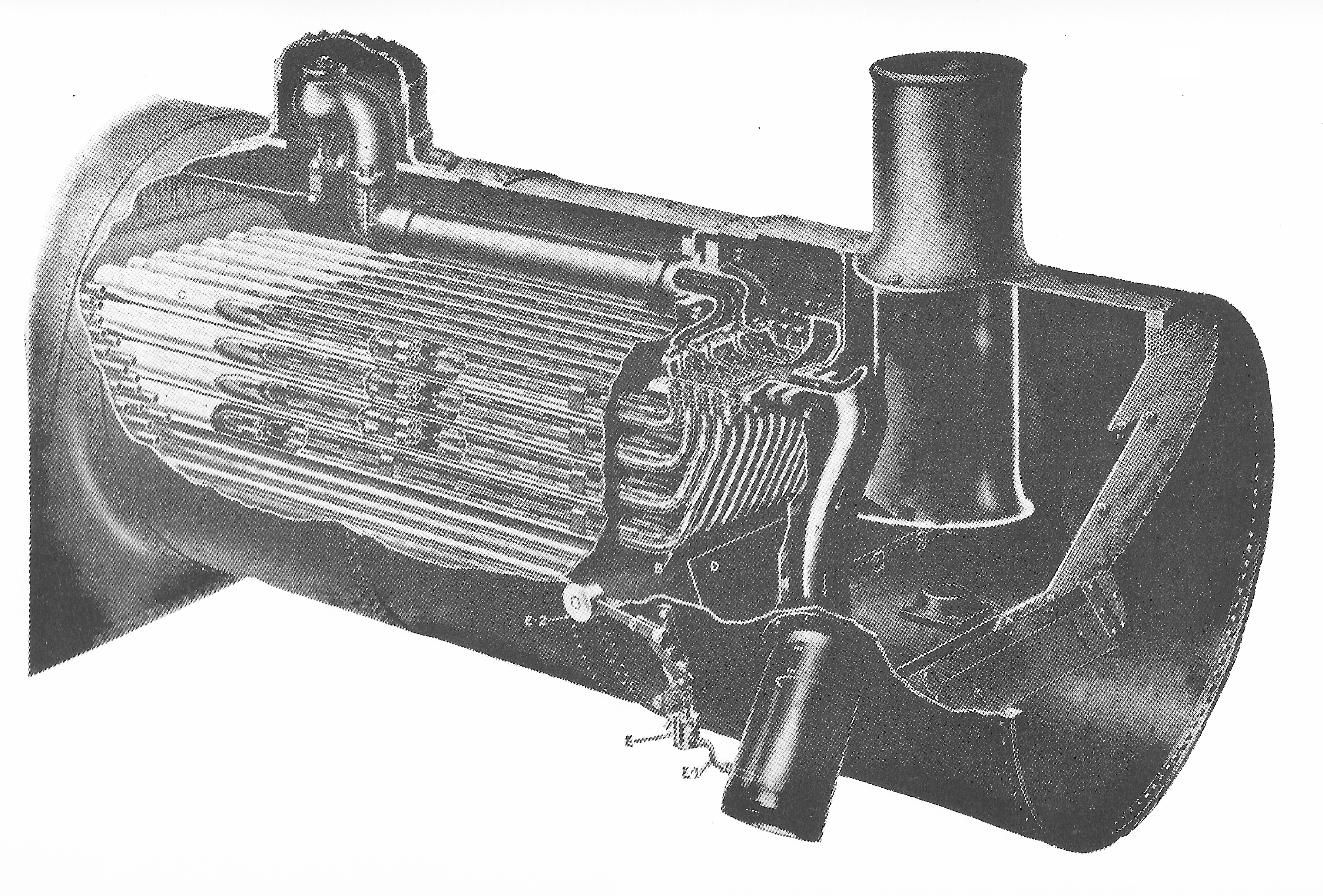

FIGURE 3: This series of illustrations depict a typical arrangement of the superheater equipment. Note the small pipe connection in the centre illustration.
The superheater adds additional heat energy to steam that has been generated in the boiler. Steam is drawn off from the top of the boiler and routed to the superheater unit, where it is no longer in contact with the boiler water, and then additional heat is absorbed from firebox gases passing through the flues. This can increase the steam temperature by as much as 150 ˚C (300 ˚F).
The superheater tube arrangement on a locomotive with a dome throttle is depicted. When the throttle valve is open, steam passes through the dry-pipe to the saturated-steam compartment of the superheater header. From here, it flows into one side of each of the header units and after traveling back-and-forth through the four pipes of each element, it returns to the outlet connections that open into the superheated-steam compartment of the header. The superheated steam then flows to a main passage at the front of the header, which connects to the cylinder steam delivery pipes.
Tubes and flues: The tubes and flues are pipes that stretch between the front and rear boiler tube sheets. They convey the product of combustion from the firebox through the boiler to the smokebox, where they are ejected from the locomotive smoke stack. They also provide the structural integrity needed for the tube sheets to withstand the boiler pressure. Flues are larger in diameter than tubes because they need to have space to contain the superheater elements. A typical boiler tube diameter is 2¼ inches, whereas flues can be from 3½ to 5½ inches depending on the size of the superheater element used. Tubes and flues provide the boiler with the majority of its heating surface. They absorb heat by convection from the mass of hot gases passing through them.
The American Multiple-Valve Front-End Throttle was a product of The American Throttle Company Inc, of New York. The company—who also manufactured Elesco-brand equipment—eventually became associated with The Superheater Co (New York, Chicago, and Montreal). Many types of modern steam locomotives do not utilise a dome valve, but instead have an arrangement called a multiple-valve front-end throttle which places the throttle valve in the smokebox, between the superheater and the steam chests. With this arrangement, the superheater units always contain superheated steam and the distance of the steam circuit between the throttle and the cylinders is minimised. This dramatically improves the responsiveness of the locomotive to the engineer’s manipulation of the regulator. Front end is the collective term for the forward end of the boiler and the smoke box
The existence of a front-end throttle is usually externally obvious. There is a throttle rod on the engineer’s side running almost the whole length of the locomotive from the regulator lever in the cab to a crank mounted on the outside of the smokebox at the superheater manifold. The rod is normally in two parts, connected about half- and sometimes about one third of the way along its length, with a reverse-motion linkage (some call it a ‘compensating linkage’). One stated purpose of this is to neutralise the effect of differential expansion between the boiler structure (to which the cab attaches for support) and the linkage itself so that thermal expansion of the boiler cannot change the throttle setting. I have trouble imagining such thermal expansion being of sufficient magnitude to change the throttle setting. For one thing, the regulator setting at any point is held fast by a pawl engaged in a sector plate. I believe there are two prosaic reasons for the use of a reverse-motion linkage: [1] to reverse–as its name suggests–the direction-of-movement of the throttle rod, so that the camshaft in the superheater manifold rotates in the required direction, and [2] to reduce the inherent flexibility of a long rod in the horizontal plane. Note: a reverse-motion linkage would not be required if the regulator output rod was attached (in the cab) below the lever pivot rather than above it. Another use for the reverse-motion linkage is to displace the input and output levers laterally, such as when the input rod (this is the rod extending out of the cab from the regulator lever) has to run along a protruding Belpaire firebox, then change to a closer setting to the boiler for the output rod to run forward to the smokebox.
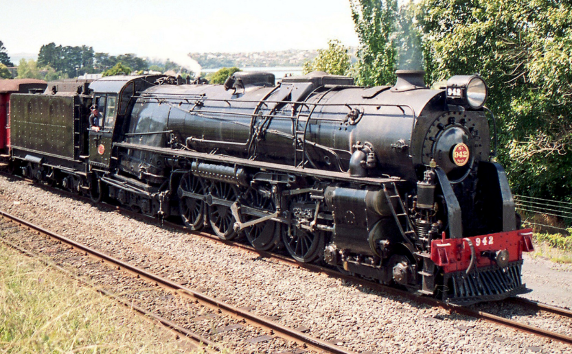
FIGURE 4: This image of a NZGR Ka-class locomotive displays the externally-visible front-end throttle arrangement. Stephen Satherley
The American Multiple-Valve Throttle (Figure 5) is just as it sounds. It has a large transverse manifold—cast integrally with the superheater header—with a camshaft that opens multiple poppet valves consecutively as the regulator setting is increased. This results in the ability to more precisely control the admission of steam to the cylinders. At a very low regulator setting, only one of the valves will be open, allowing a relatively small about of steam to enter the steam chest. While—assuming the proper valve setting (reverser cut-off)—sufficient steam could be introduced in this state to allow the locomotive to move, given the rate of expansion needed to fill the steam chest the pressure therein would never be able to equal the boiler pressure and with each piston stroke would be quickly used and exhausted. As a steam locomotive accelerates, the steam is used faster and faster with each piston stroke and thus more steam must be admitted to the cylinders. Pulling back on the regulator lever sequentially opens other valves in the manifold, permitting an increase in steam supply to the cylinders.
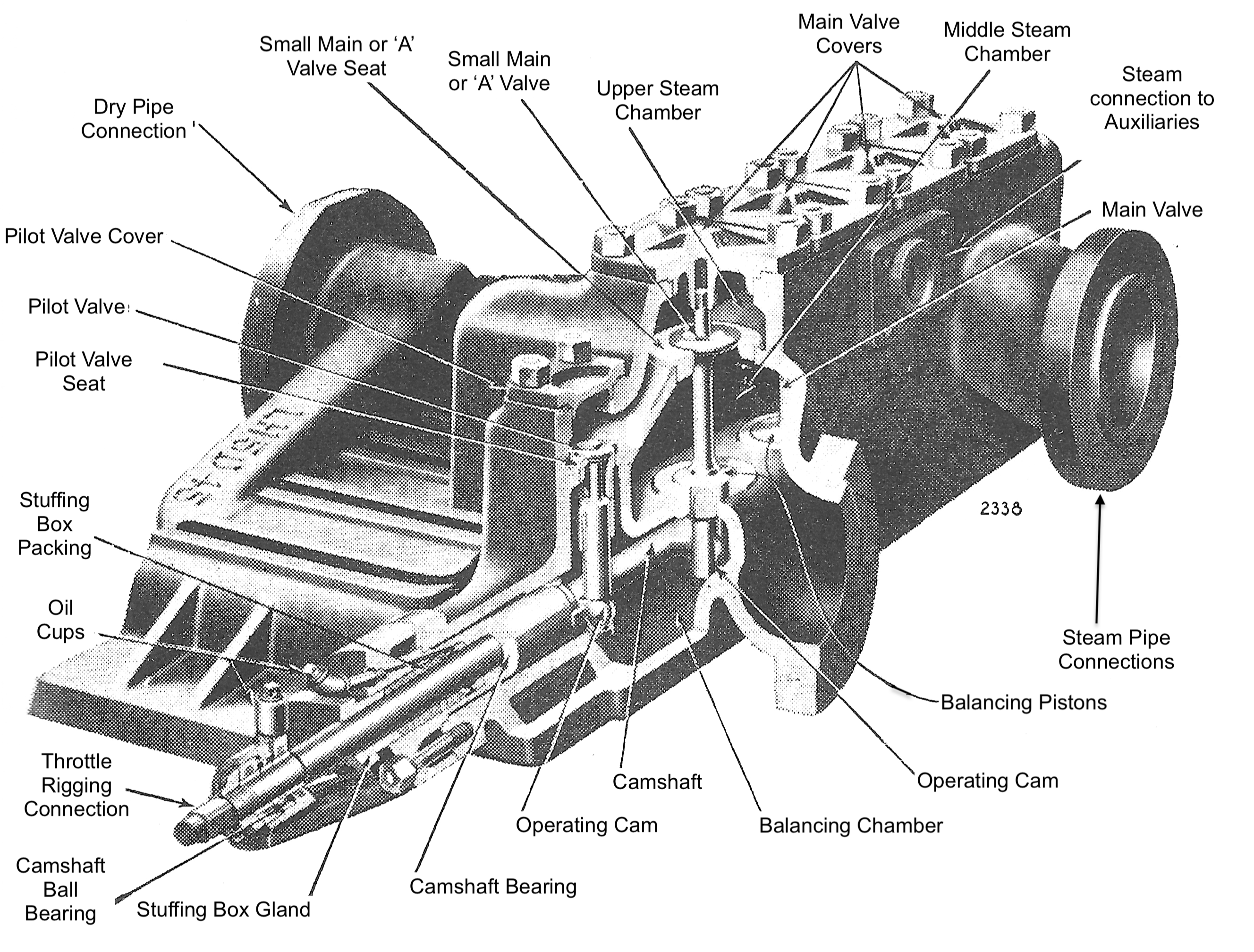
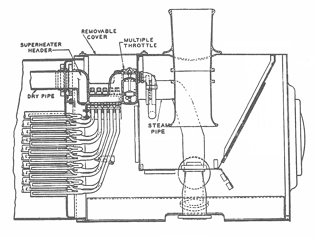
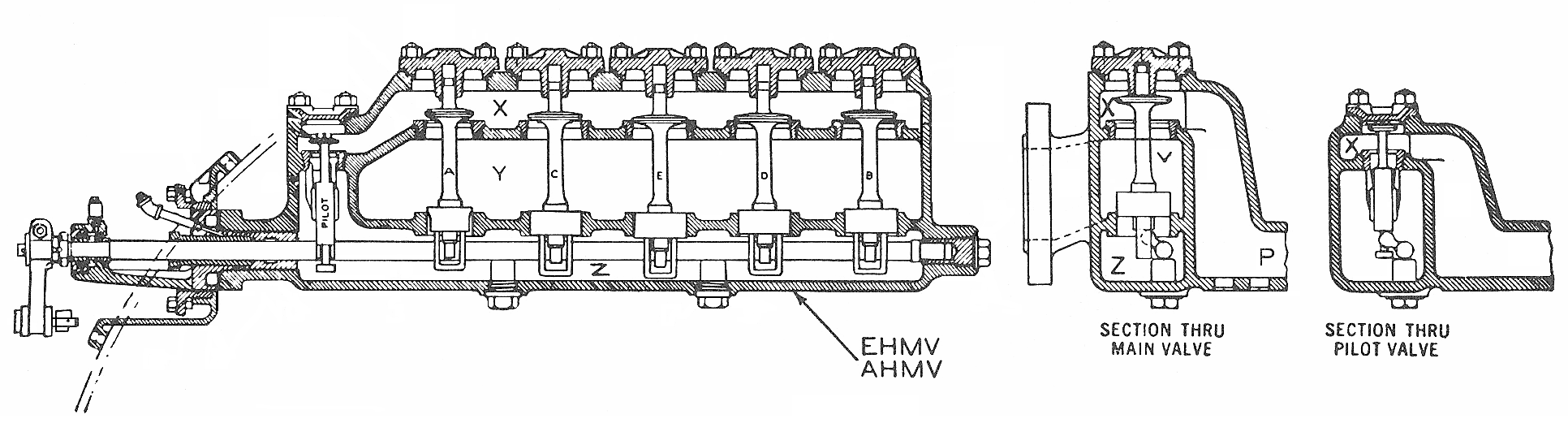
FIGURE 5: This series of illustrations depict various views of the Multiple Valve Front-end Throttle. Note the ‘Steam Connection To Auxiliaries’ label in the upper illustration.
The arrangement of a front-end throttle is depicted. The small pipe connection shown ahead of the throttle (referred-to in the caption for Fig 3 and also in the caption above) is an outlet that carries superheated steam to the auxiliary devices of the locomotive, such as air compressors and turbo-generator.
Before the front-end throttle came into use, it was the practice to use a damper in the smoke box to prevent the superheater elements from being burnt by combustion gases when the throttle was closed and no steam was passing through them. However, this damper is not required on a locomotive which is equipped with a smokebox throttle, as this arrangement carries steam in the superheater elements at all times, thereby protecting them from being burnt.
The multiple throttle provides for a series of small, single-seated, steel valves that are located in the forward part of the superheater header. After the steam from the dry-pipe has passed through the superheater header, it enters the upper steam chamber above this line of throttle valves. There are three longitudinal chambers extending across the front of the header, arranged one above the other. These are shown at X, Y, and Z. The upper chamber, X, is a part of the superheated-steam section of the header. At one end of this chamber, or on the front face of the header (which is the preferred location), is the flange connection to the auxiliaries mentioned above, so that superheated steam is always available for them. The steam supply pipe to the auxiliaries, which bends under the left side steam pipe (centre illustration, Fig. 3), is attached to the flange on the superheater. The middle chamber, Y, connects with the steam pipes leading to the engine cylinders. The third chamber, Z, is without outside connection, it is used entirely for balancing the force on the throttle valves.
There are three or more main valves, according to the size of the locomotive. When opened, these valves admit steam from the upper to the middle chamber. At the extreme right-hand end of the throttle valve manifold (left side on the illustration) is a small valve, known as the ‘pilot valve’, which admits steam from the upper chamber to the balancing chamber when the throttle is being opened. Each of the larger or main valves has a balancing piston on the lower end of the stem, which fits loosely in the guide between the middle and the balancing chambers. The main valves are all of the same size, except the A valve (usually located on the right side, but may differ on LH-drive locomotives such as in NSW, Australia), which is slightly smaller in diameter.
The valves are similar in design to those used in automobile engines. Valves of this type have proved their ability to resist high temperatures and remain tight under the severest kind of service. Therefore, this type of valve is well adapted to the less severe conditions of locomotive operation. The valves are opened and closed consecutively by a camshaft, and are so balanced that a minimum of effort is required to lift them.
At the first movement of the regulator lever, the pilot valve is raised and admits steam from the upper (live steam) compartment to the balancing chamber, immediately building up pressure under the balancing pistons equal to that in the upper compartment. This ensures ease of operation. Further movement of the regulator lever opens the small main valve A, allowing steam to pass to the cylinders. The cams on the shaft are so graduated in contour that, when the first valve has partially opened, a second valve starts to open, and so on until all have opened when the regulator lever is in the full-open position. Thus, steam flows from the superheated-steam compartment of the header into the middle chamber of the throttle, and thence to the cylinders. Closing takes place in reverse order.
Additional Items
Valve events: There are four valve events that occur in a steam locomotive cylinder:
-
Admission – steam is admitted to the cylinder, where it pushes against the piston.
-
Cut-off (Expansion) – steam admission is stopped and the valve seals the cylinder. The steam already in the cylinder is allowed to expand which provides further force against the piston.
-
Release (Exhaust) – the exhaust port is opened and steam begins to leave the cylinder. The piston reverses direction and then pushes the exhaust steam out the exhaust port. The resistance it encounters doing this is called back-pressure.
-
Closure (Compression) – the exhaust port is closed. Some steam remains in the cylinder and is compressed as the piston pushes against it – reaching boiler pressure. This acts to cushion the piston as it slows and begins to reverse its direction of movement. The energy lost in compressing the trapped steam is regained at cut-off when the steam in the cylinder is allowed to expand.
The steam circuit: This is the name given to the path taken by steam once it has been drawn from the top of the boiler by a collector and routed to the cylinders. On a modern locomotive with a front-end throttle, the various piping and appliances would include the following, in order: dry pipe > superheater header (wet side)> superheater elements > superheater header (dry side) > throttle > delivery piping (to steam chests), and (finally) > the piston valves.
Good design practice called for minimising obstructions, sharp bends, or anything that might restrict the steam flow. Good maintenance practice involved periodic cleaning of the interior surface of the steam delivery pipes. In NZGR practice, this latter would not have been done often. The object was to deliver steam to the cylinders with as little pressure loss as possible.
Bibliography:
White, John H. Jr. A History Of The American Locomotive – Its development: 1830-1880. New York: Dover Publications, Inc., 1968.
Buell, D.C. Basic Steam Locomotive Maintenance. Omaha: Simmons-Boardman Publishing Corporation, 1980.
Prior, Frederick. J. (M.A.) Modern American Locomotive – Construction And Operation. Omaha: Simmons-Boardman Publishing Corporation, 1925.
(Unacknowledged). Fundamentals Of The Steam Locomotive. Omaha: Simmons-Boardman Publishing Corporation, 1949.
Johnson, Ralph P. (M.E.) The Steam Locomotive – Its Theory, Operation, And Economics. Omaha: Simmons-Boardman Publishing Corporation, 1942.
MORE ON SUPERHEATING
A Brief History of locomotive Superheating (compilation)
And for further reading on this subject:
Melesco_Superheater_Instructions
AIR BRAKING – THE PNEUMATIC TRANSMISSION OF ENERGY
This section is intended to provide coherent explanations of locomotive air brake functionality. I hope they’re useful. Note though, that these descriptions apply mostly to previous levels of locomotive technology. Micro-processor control has nowadays changed some of this functionality.
The Air Compressor
All air pressure on a locomotive is sourced from the Main Reservoir, and the Main Reservoir is charged by the locomotive air compressor. The reason for using pneumatics—or any other type of energy transmission on a machine—is to perform work. This requires the application of kinetic energy to a resisting object resulting in the object moving through a distance. In a pneumatic system, energy is stored in a potential state as compressed air. Working energy (kinetic energy and pressure) results in a pneumatic system when the compressed air is allowed to expand. For example, if a reservoir is charged to 100 PSIA with compressed air, then—when the valve at the reservoir outlet is opened—the air inside it expands until its pressure equals that of atmosphere.
Working energy transmitted pneumatically must be directed and under complete control at all times. If not, useful work will not be done and machinery or machine operators might be harmed. One of the advantages of transmitting energy pneumatically is that it can be controlled relatively easily by using valves.
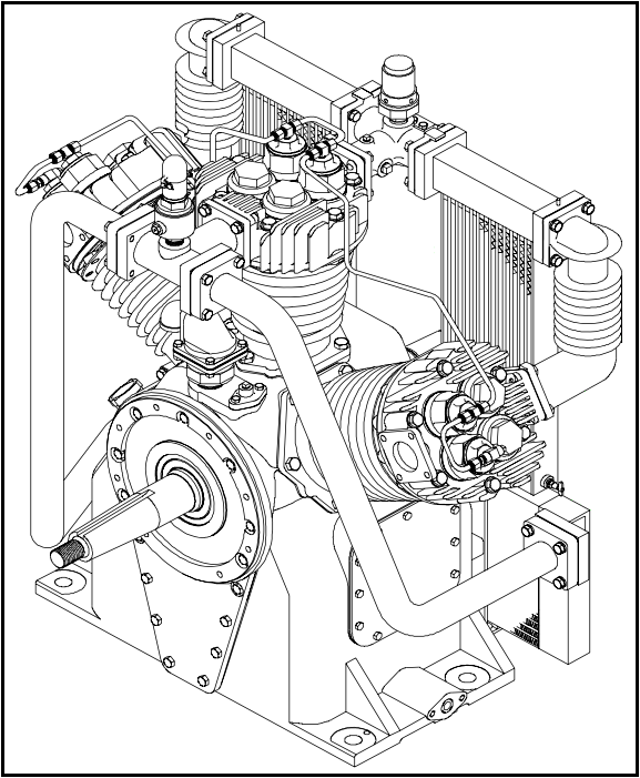
Air expansion takes the form of airflow. Therefore, to perform any applicable amount of work, a device is needed that can supply an air reservoir with a sufficient amount of air at a desired pressure. This device is a positive-displacement compressor (Fig. 1) that basically consists of a movable member (in this case a piston) inside a chamber (the piston bore, or cylinder). The piston is connected to a crankshaft, which is in turn connected to a prime mover (electric motor or internal combustion engine).
Valves at inlet and outlet ports, allow air to enter and exit the chamber. Locomotive air compressors will have two or more chambers (cylinders). The compressor will usually consist of two low-pressure cylinders and one high-pressure cylinder; the pistons of all three cylinders being driven by a common crankshaft. The two low-pressure cylinders are set at an angle to the vertical high-pressure cylinder so that all three can be aligned laterally, taking up less space on the locomotive. Air from the low-pressure cylinders is pumped through an intercooler (basically a radiator) to be cooled before entering the high-pressure cylinder. The intercooler is provided with a pressure gauge and relief valve.
At the top of each compressor cylinder is the valve head in which the inlet and discharge valves are located. Both are simply thin metal flaps – one mounted underneath and one mounted on top of the valve plate. As the crankshaft pulls the piston down, an increasing volume is formed within the chamber – in other words, a vacuum is created above it. This allows outside air at atmospheric pressure to push open the inlet valve and fill the area above the piston – the trapped air in the chamber expanding, reducing its pressure. With the piston at the bottom of its stroke, the flow of air coming in ceases, and the inlet valve closes.
The piston starts its upward movement to reduce the air volume, which consequently increases its pressure and temperature. As the piston moves up, the air above it is compressed, this force holding the inlet valve shut and pushing the discharge valve open, allowing the pressurised air to pass. The air moves from the discharge ports of the low-pressure cylinders to the inlet ports of the high-pressure cylinder, and then from the discharge ports of the high-pressure cylinder to the No. 1 Main Reservoir.
All of the process just described happens extremely quickly… in the time it takes for the compressor crankshaft to rotate twice.
Pressure in a pneumatic system must be controlled at two points – after the compressor and after the air-receiving reservoir. Control of pressure is required after the compressor, as a safety feature for the system. Its control at an air-receiving reservoir is necessary so that an actuator (such as a valve) receives a steady pressure source without wasting energy.

Energy delivered by a compressor is not generally used immediately, but is stored as potential energy (Fig. 2). In most instances, a compressor is designed into a system so that it operates intermittently. A compressor usually delivers compressed air to a reservoir until a high pressure is achieved, at which point it is shut down (or made to cease pumping). When air pressure in the reservoir decreases, the compressor starts up or cuts in again and recharges it. Such intermittent compressor operation is a power-saving benefit for the system.
A common way of sensing reservoir pressure and for controlling actuation and de-actuation of locomotive compressors that are operated by an electric motor has historically been with a pressure switch. System pressure is sensed by use of a small spring-loaded piston within the switch housing. This was called the compressor governor. With pressure in the system at its low level, the spring moves the piston to close a contact causing an electrical signal to turn on the compressor. As the compressor pumps and pressure in the reservoir rises, this pressure eventually reaches its high level and overcomes the force of the piston spring. This breaks the electrical contact, shutting down the compressor.
Diesel locomotive air compressors that are mechanically driven (from the diesel engine crankshaft or via a flexible coupling from the armature shaft of the main generator) use a different mechanism to turn compressor pumping on and off. Since—in this case—the air compressor is directly connected to the engine, it is in operation at all times when the engine is running, although it is not always required to pump air.
To deal with this, a device called an unloader is provided in the heads of both high- and low-pressure cylinders to prevent the compression of air and its delivery to the Main Reservoir system. The unloaders are activated by an auxiliary Main Reservoir pressure feed. The unloader accomplishes its task by holding open the intake valves of all compressor cylinders. The low-pressure cylinders continue to suck air in but will blow it right back out through the intake strainer without it being compressed. When the air pressure supplied to the unloader is cut off, the unloader releases the intake valves and the compressor resumes pumping.
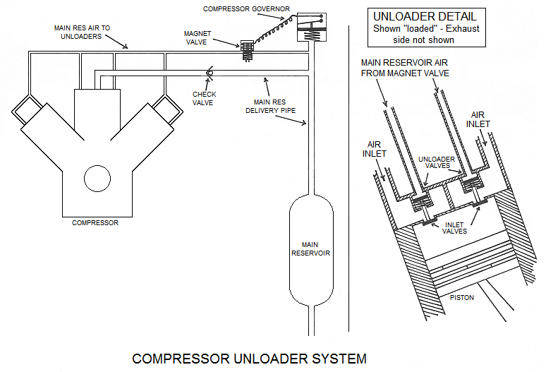
The pressure to the unloader valve is supplied from the compressor governor. There were a variety of types, from a straight air-operated valve to an air-operated valve combined with an electrical switch (for the MU compressor signal), to using a pressure switch to control a magnet valve.
The unloader feed is taken from the Main Reservoir to a switch housing (Fig. 3) that contains a small piston and a set of contacts. The small piston is influenced by the Main Reservoir pressure and opposed by a spring. As the compressor pumps and Main Reservoir pressure rises, the piston overcomes the spring force and closes the electrical contacts. This energises the magnet valve, which opens to permit Main Reservoir pressure to flow to the unloader valves, which now hold the compressor inlet valves open, thus ‘unloading’ the compressor. As Main Reservoir pressure is used up on the locomotive and the pressure drops, the compressor governor spring causes the electrical contacts to open and de-energise the magnet valve, which releases air pressure in the unloader line. The compressor inlet valves are now able to open and close normally, and the compressor pumps air as the cycle begins again.
The compressors are generally two-stage (also known as ‘compound’). As stated, two low-pressure cylinders pump into one high-pressure cylinder and there is an intercooler between the two stages to lower the air temperature as it is pumped from the low- to the high-pressure cylinder.
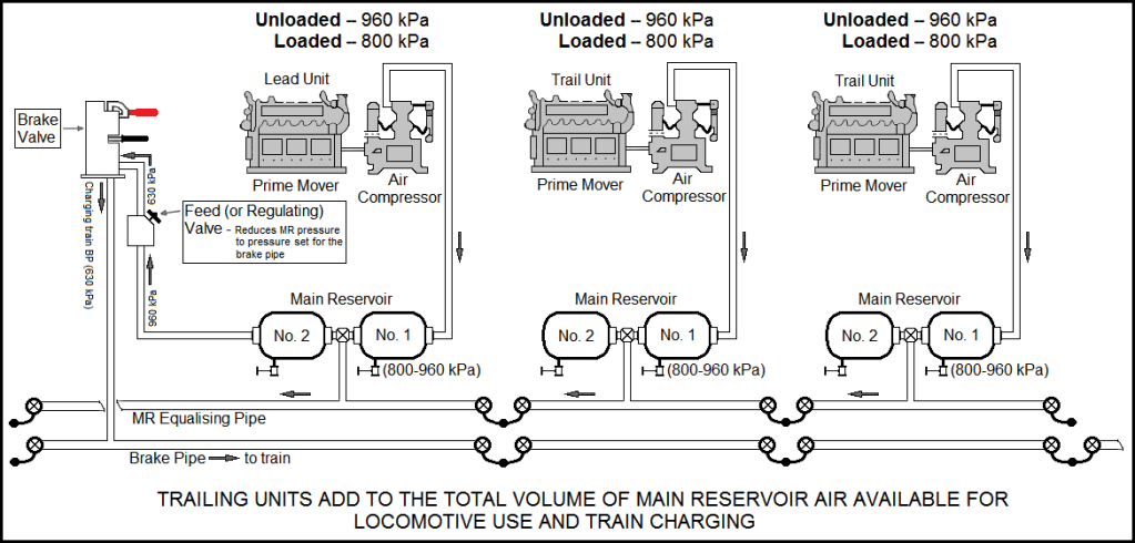
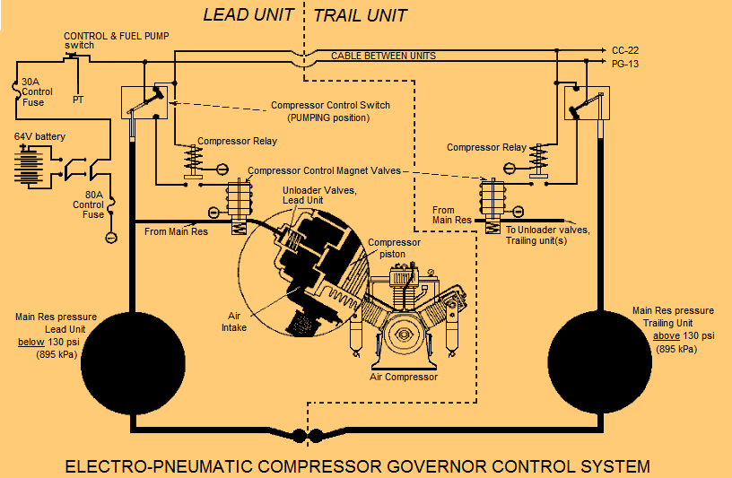
The loading and unloading of the compressor in each locomotive of a multi-coupled consist (Fig. 4) is controlled by an electro-pneumatic system. The electrical arrangement is such that all compressors in the locomotive group are synchronised to ‘load’ (pump air into their respective Main Reservoirs) when the Main Reservoir air pressure in any one unit drops to its ‘low’ setting… usually around 800 kPa. When the air pressure in all Main Reservoirs reaches the ‘high’ setting (usually around 900 kPa), the compressors will ‘unload’. Each unit is equipped with a compressor control switch (CCS, see Fig. 5) actuated by Main Reservoir pressure and a compressor relay (CR). A compressor control wire (CC) runs throughout the locomotive and connects the compressor relays in each unit in parallel.
That is why—on older locomotives—if the governor fails and the compressor will not pump air, a crew member can manually cut out the governor and allow the compressor to pump continuously. The safety valve will limit the pressure to protect the air system.
Maximum pressure developed by a compressor is designed to be regulated by a control system that senses discharge or reservoir pressure. In the case of an emergency (such as the failure of a control system to function properly) a positive-displacement compressor system is generally equipped with a safety relief valve, which is a ‘normally-closed’ valve.
The poppet of the safety relief valve is seated on the valve inlet. A spring holds the poppet firmly on its seat. Air cannot pass through the valve until the force of the spring biasing the poppet is overcome. Air pressure at the compressor outlet is sensed directly on the bottom of the poppet. Should this pressure become undesirably high, the spring will be compressed, the poppet will move off its seat, and air will exhaust through the valve.
A safety relief valve on a compressor is designed only to be a safety device and is not intended to operate frequently.
Air Brake System Schematic Diagrams
This section contains air brake system information describing various aspects of air brake system layout. The diagrams are not to scale.
Some of the diagrams you will see here are simplified graphic images while others are variations of Fluid Power System Piping and Instrumentation Diagrams (P&IDs) – the ‘fluid’ in this case being compressed air. A P&ID shows the piping and related components of a physical process flow. Where this desired process is the operation of an on-board air braking system, the P&ID will be a schematic illustration of the functional relationship of piping, instrumentation and equipment components.
P&IDs are schematic diagrams used by field technicians, engineers, and operators (locomotive staff) to better understand how the components are interconnected and to explain how the processes work. They are line drawings comprising a series of symbols and connections that represent the actual components in a fluid power system. These symbols cannot be relied-upon as models because they aren’t necessarily drawn to scale or geometrically accurate.
Some of the main element types depicted in a P&ID are Directional Control Valves (DCVs), actuators, wires, pipes and pumps. A DCV (which may be a Double Check Valve or a Relay Valve) has two fundamental positions; namely a ‘Normal’ position (to which the valve might return on removal of the actuating force) and a ‘Working’ position (which is the position the valve adopts when the actuating force is applied). Other DCVs may have 3 or more positions that can be spring-centred, with two Working positions and a Normal position. DCVs are classified according to: (1) the number of ports, (2) the number of possible positions, (3) the various actuating methods, and (4) the type of spool (if applicable). In a locomotive air brake set-up, these positions will usually be pipe connections or exhaust ports.
Training Using Schematic Diagrams
Here is an example of a P&ID schematic as it might be applied to locomotive air brake training. I acquired this drawing—in a very second-hand state—from an ex-NZR locomotive engineer many years ago in Western Australia (thanks Mark). He had received it during training in New Zealand. Later, when I was compiling my air brake history and reference work (see my Publications page), I thought it would be useful to redraw it in a tidy form. Figures 6 and 7 show the ‘before’ and ‘after’ versions…
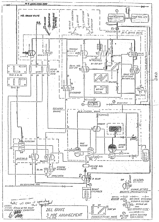
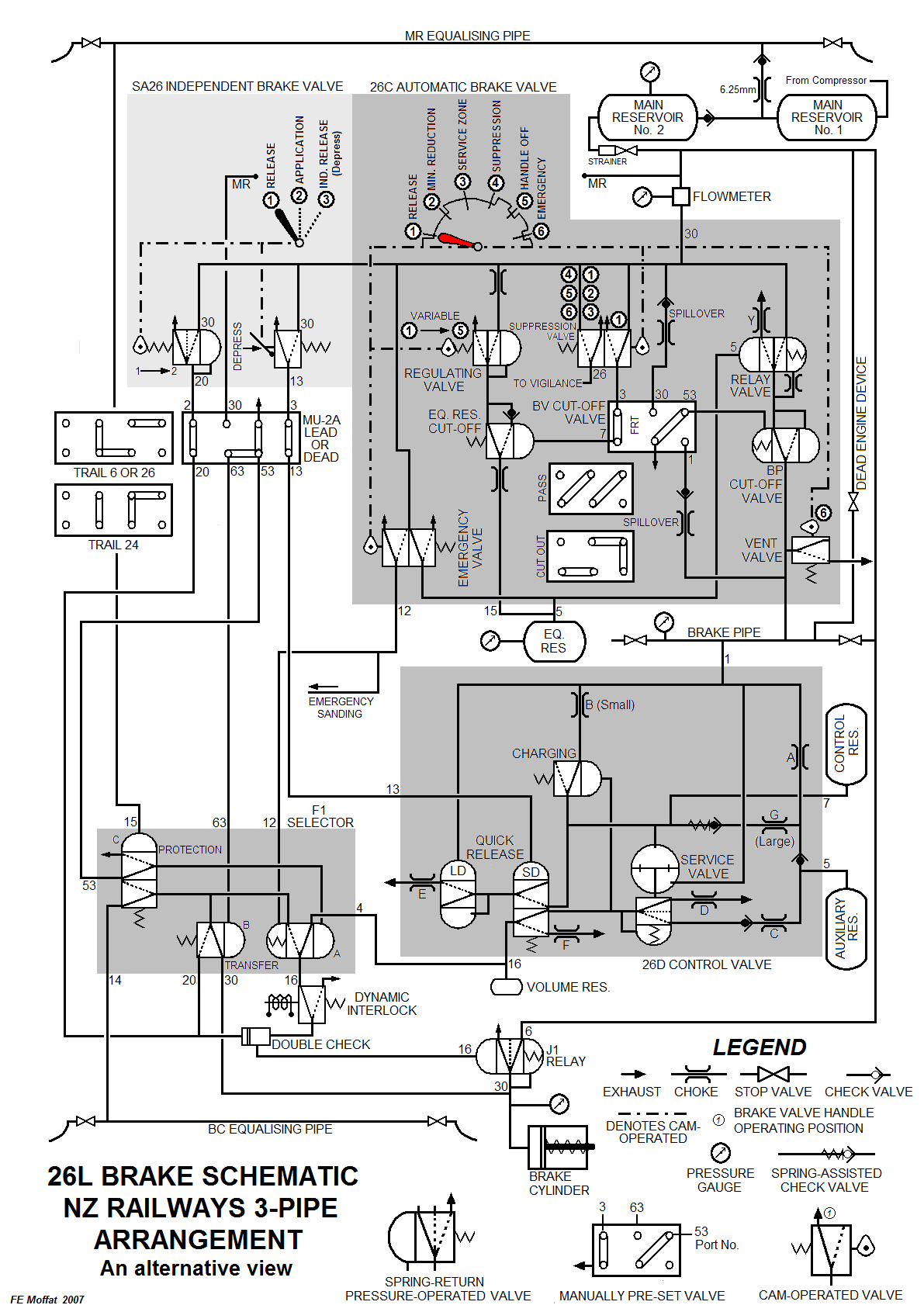
The following diagrams depict a version of a P&ID schematic for 26L air brake instruction. The diagrams depict simplified renderings of the various valves. These are designed to show what the interrelated components do and how they achieve these tasks rather than what the components themselves physically look like. There’s a distinction (for an interested locomotive engineer) between needing to know how the internal construction of a valvular component looks versus what that component’s role in the total process is. These diagrams show the latter. Careful study and referencing the instructive text to the diagrams is the only way to achieve a useful level of understanding.
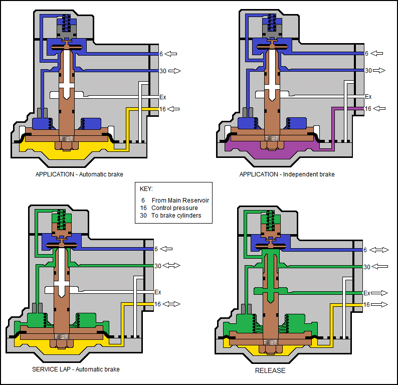
Looking to Fig. 8 (Brake Pipe Charged, Independent Brake Released):
-
The 26C Automatic brake valve (ABV) element A is shown within a dark grey box. The system is charged and train brakes are released. Equalising Reservoir (ER) pressure [yellow] and Brake Pipe (BP) pressure [red] are the same value, thus the BP is closed off within the Relay Valve portion, BP pressure has no path to Exhaust, and the BP is held fully-charged. This balanced condition of the Relay valve portion is depicted by the two brown counter-facing arrows, showing that both the ER and BP forces are working against—and balancing—each other.
-
The Regulating valve portion is also balanced (see brown counter-facing arrows). In this case, rather than two separate air pressures countering each other, the internal valvular components have ER pressure countered by the spring pressure created by the ABV handle being at the RELEASE position (‘on cam’). Thus ER pressure has no path to Exhaust and is held constant.
-
The Independent brake valve (IBV) element B and associated brake cylinder Relay valve (EL or J-type) C are depicted as discrete components separate from the ABV – the IBV being within the locomotive cab whereas the brake cylinder Relay valve is situated elsewhere as part of the locomotive air brake schedule. The IBV handle D is at the RELEASE position, so the assembly is ‘off cam’, permitting spring pressure (acting in the direction shown by the brown arrow) to condition the IBV assembly such that Control Pipe 20 (or Independent Application and Release pipe)—which is connected to the locomotive Relay valve—is exhausted. In this condition, the locomotive Relay valve is positioned to exhaust the locomotive brake cylinders.

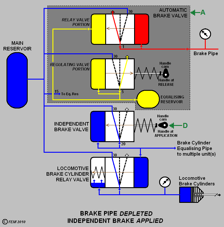
Looking to Fig. 9 (Brake Pipe Depleted, Independent Brake Applied).
-
The 26C ABV element A is shown within a dark grey box. The ABV handle has been moved to initiate a brake application and BP pressure is reducing. With the ABV handle having been moved away from its RELEASE position, the Regulating portion has come ‘off-cam’, and spring force (depicted by the brown arrow)—being now relieved—is overcome by ER pressure. This results in the Regulating portion being conditioned to permit an exhaust of ER pressure. The amount of the reduction is conditional on the degree by which the ABV handle has been moved into the SERVICE zone. ER pressure in the Regulating portion depletes to a point where the spring pressure (existing as a result of the ABV handle position) can sufficiently overcome the ER pressure to nudge the Regulating portion assembly back to a neutral position that cuts off the ER exhaust. In this state, the Regulating portion has lapped.
-
It should be understood that all of this process—from initial ABV handle movement away from RELEASE position, until the ER pressure reduces and the Regulating portion laps—takes only a few seconds. This is because the volume of ER air in the system is quite small.
-
ER pressure acting in the Relay portion is also reduced. This permits BP pressure to condition the Relay portion (see direction depicted by brown arrow) to connect the BP to Exhaust and reduce BP pressure. This applies the train brakes. ER will stabilise at the reduced value according to the ABV handle position, at which point ER and BP pressures within the Relay portion balance, and internal spring pressure will return the assembly such that the exhaust of BP pressure is cut off. The Relay potion thus assumes its LAP position.
-
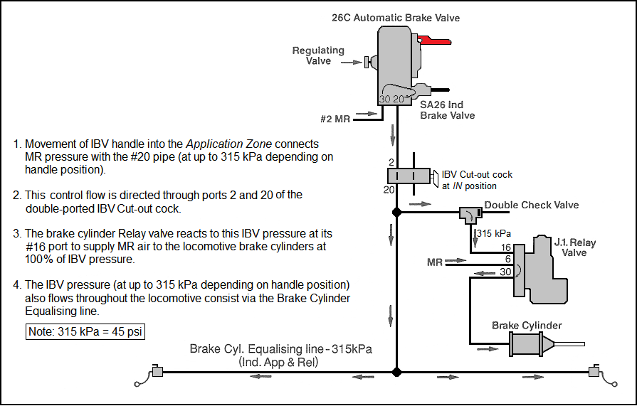
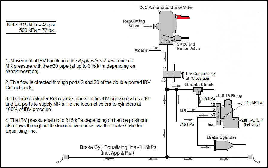
In this graphic, the IBV handle D has been moved into the APPLICATION zone. The IBV is thus conditioned to connect Main Reservoir (MR) pressure into Control Pipe 20 and thus the locomotive Relay valve. This is known as a ‘control’ pressure. As MR pressure flows to the locomotive Relay valve it also develops within the IBV. When this increasing pressure equals that supplied into the Control Pipe, the IBV assembly will move under the influence of internal spring pressure to assume a neutral position and cut off the supply of MR pressure. In this state, the IBV has ‘lapped’.
-
At the Relay valve the control pressure being supplied overcomes spring pressure (depicted by the brown arrow) and opens a MR connection to the locomotive brake cylinders. The locomotive brakes are applied. As MR pressure to the brake cylinders increases, it also develops within the Relay valve until—with the aid of a spring—the Relay valve is conditioned to cut off the supply of MR air. The Relay valve assembly will adopt a neutral state and ‘lap’. Brake cylinder pressure will be held steady at a value consistent with the degree of IBV handle movement into the APPLICATION zone.
The next diagram (Fig 10) is intended to reveal the similarity between the operating intention of the Independent and Automatic brake valves. For both there is an ‘activating’ action (brake valve handle operation) and a ‘response’ action (the supply of a brake application signal) which occurs via the reaction of a relay valve.
Independent application: Handle moved into APPLICATION ZONE > supply of a control air pressure (from the MR) to the locomotive brake cylinder relay valve > which reacts to this control pressure signal to admit air pressure (from the MR) to the locomotive brake cylinders.
Automatic application: BV handle away from RELEASE (usually just into the SERVICE ZONE) >creates an Equalising Reservoir pressure reduction at the brake valve Relay valve > creates a Brake Pipe pressure reduction via the brake valve Regulating valve > results in a brake application on trailing vehicles.
Be aware that the SA26 locomotive Independent brake valve is also a ‘regulating’ valve. As with the Regulating valve portion within the 26C ABV, its pressure can be set and adjusted as desired. This reveals a generic process that is helpful to remember when one contemplates how these devices achieve their tasks.

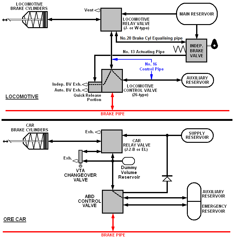
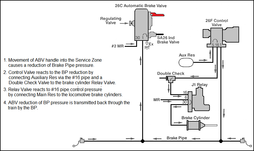
Fig. 11 depicts and compares a Pilbara locomotive and ore car brake scheme. This is an American 4-pipe system with a 26-F control valve on the locomotive and ABD or ABDW control valves on the trailing rollingstock. The diagram reveals the similarities in operation of these two sub-systems through the interaction of Relay and Control valves. Both the locomotive Independent and car brakes are shown released.
The locomotive control valve has a dual function;
[1] It will react to a Brake Pipe reduction and create a locomotive brake application (in the same manner as will a car triple or control valve) and…
[2] It will react to an actuating signal from the Independent brake valve to release such an Automatic application.
So it can be seen that the main difference, in this regard, between a locomotive and a trailing vehicle is that the locomotive has an extra device—the Independent brake valve—by which to initiate its brake application.
On a North American 4-pipe system (they call it a ‘two-pipe system’, because the BP and MR pipes are a given and therefore not considered in referring to how many pipes there are) the No. 20 pipe is known generally as the Independent Application & Release pipe (or ‘line’) or the Brake Cylinder Equalising pipe, whereas on a 3-pipe system, such as in New Zealand, the No. 20 pipe has traditionally been referred-to as the ‘Control’ or ‘Equalising’ pipe.
This diagram can also be interpreted for an Australian state railway system using a 500 kPa (70 lb) Brake Pipe.
The Independent Brake And The Locomotive Brake Cylinder Relay Valve
The following explanation is based on the North American railroad environment of the Pilbara iron ore industry. Readers not from this environment will be able to interpret the detail by using a 500 kPa Brake Pipe pressure and alternative devices, such as different locomotive Control Valves and car Empty/Load valves.
Locomotives—especially high-horsepower units, by nature of their heavy weight—can be braked at extremely high brake ratios. A six-axle locomotive weighing 190 tonnes has a net axle loading of over 30 tonnes. A locomotive such as a GE Dash 8 can produce approximately 38,000 lbs (17,237 kg) of net braking force without sliding the wheels. By comparison, a typical loaded 130-tonne iron-ore car can produce only 12,000 lbs (5,443 kg), or approximately ⅓ the force of a locomotive.
It is worth noting that at 20% adhesion and low speeds, the Independent brake is as efficient as is the extended-range dynamic brake at slightly higher speeds (i.e. 15 – 40 km/h).
Due to its heavy weight on driving wheels, the diesel-electric locomotive has excellent static holding capabilities on grades. The Independent brake is an excellent means for holding a train after a stop on a grade while the brake pipe and air brake system is being recharged. Should the Independent brake not prove to be sufficient, though, then hand brakes may have to be set.
Locomotive brake systems develop high braking forces through heavy-duty brake rigging and truck-mounted brake cylinders. Typically the materials used in locomotive brake rigging are of a higher strength than that found in conventional freight cars. Levers are short and direct, resulting in a nominal efficiency of around 75%.
There are basically two primary brake rigging configuration is in use today. They are clasp rigging and single shoe rigging. Clasp rigging (using two blocks per wheel) is normally used with cast-iron blocks. High-horsepower locomotives today generally use single shoe rigging and High-Friction composition blocks.
Locomotive brake ratios
The Association of American Railroads (AAR) specifies a minimum net braking ratio of 20% with 310 kPa (45 psi) control line pressure, provided through the #20 Independent Application & Release (on four-pipe locomotives, this may be labelled Brake Cylinder Equalising). However to achieve satisfactory grade holding ability, most railroads increase the ratio slightly above this minimum.
Static holding ability is not the only consideration in safe train handling. The locomotive brake must also work in harmony when the train is moving at higher speeds. On a graph the friction v speed curve shows that brake shoe friction drops off substantially at speeds in excess of 3 – 5 km/h (particularly for the cast-iron shoe). At higher speeds the locomotive brake cannot transfer as much braking force to the rail as it can at lower speeds or when stopped. To avoid wheel-sliding when moving, the Automatic brake ratio needs to be less than the Independent ratio. In order to obtain these different ratios, a differential Relay Valve (most commonly a J-type, see below) is used.
J-type relay valves
The J-type brake cylinder Relay Valve is a device that receives large volumes of air from the Main Reservoir (MR) and delivers and maintains output pressures (which are proportional to the control pressure previously mentioned) to the locomotive brake cylinders. The output pressures may be equal to, less than, or greater than the control pressure. In electrical terms, it is analogous to using a low-voltage relay to control a high voltage/high amperage contactor.
The output pressure from the J-type Relay Valve is supplied directly to the brake cylinder. The control pressure that activates the Relay Valve originates at the Independent Brake Valve (IBV) and is proportional to the position of the handle – typically varying between zero and 310 kPa, although some railroads may differ slightly. The control pressure can also originate from the 26-F Control Valve, with output being proportional to the brake pipe (BP) reduction. In simple diagrammatic terms, the J-type Relay Valve performs as shown in Fig 12.
The most basic J-type—the J.1—provides an output volume of air that is directly proportional to the control pressure. For instance, a Full Application control pressure (low-volume, 310 kPa/45 psi) will result in 310 kPa at a high-volume into the brake cylinders. This is called a 100% ratio of input-to-output.
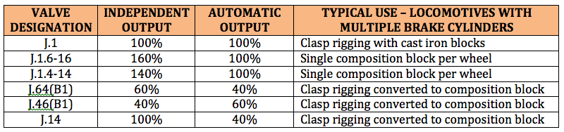
As mentioned earlier, it is desirable to obtain different brake ratios for Automatic and Independent braking. By adding an extra diaphragm to the J-type Relay Valve, additional step-up or step-down pressures can be obtained. Most typically, pressure is stepped up or down by 40% or 60%. Some common J-type Relay Valves are listed in Fig. 13.

How the J.1. Relay Valve functions
As stated previously and shown in Fig. 12, control pressure comes from either the Independent Brake Valve or the Control Valve. The control pressure enters port 16 at the Relay Valve and flows to the bottom of the diaphragm. This pressure moves the diaphragm upward, causing the hollow stem valve to also move upward. This action closes off the path to exhaust, opens the inlet valve, and admits MR air via port 6. This pressure flows through the Relay Valve and exits via port 30 to the brake cylinders.
Similarly, a reduction of control pressure (i.e. releasing or part-releasing the Independent brake) will permit the diaphragm to move downward, exhausting brake cylinder pressure in proportion to control pressure.
The J-type Relay Valve is self-lapping. Output air pressure (port 30 to the brake cylinders) is also connected to a chamber above the diaphragm. As brake cylinder pressure develops, it also develops in this upper diaphragm chamber. When the desired output value is attained and this pressure exists on both sides of the diaphragm, spring pressure moves it slightly down so that the hollow stem comes away from contact with the inlet valve, allowing the inlet valve to close. Should brake cylinder pressure drop (e.g. through leakage), the diaphragm will again move upward, opening the inlet valve and admitting more MR air until pressure across it are again equal.
Note again, that—for the J.1. relay Valve—when supplied from an Independent brake application, control air is MR pressure and is delivered to port 16 of the Relay Valve via pipe 20, the Indep Appl’n & Release pipe. When locomotive braking results from an Automatic brake application, control air is Auxiliary Reservoir (AR) pressure and is supplied via the Control Valve through pipe 16.
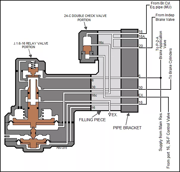
Step-up or step-down relay valves have two diaphragms, and use one or both of them to achieve the necessary pressures during Automatic or Independent applications. Fig. 15 shows the internal configuration of a J.1.6-16 step-up Relay Valve. By using a Double Check Valve (often seen depicted as the 24-C DCV portion, which is attached to the Relay Valve filling piece) an Independent application feeds control pressure through ports 16 and 16c to supply both diaphragms, thereby obtaining 160% of control pressure.
Another feature of the J-type Relay Valve is termed the in-shot portion. The in-shot feature is used on step-down relays and is designated with the letter B in the suffix. Step-down Relay Valves can create pressures less than 70 kPa (10 psi) in the brake cylinder, which isn’t enough to place the shoe against the wheel. The in-shot feature is an added boost to put the brake shoes against the wheel. Typically, in-shot will add roughly 28 – 42 kPa (4 to 6 psi) to the delivery pressure as called-for.
Regardless of the J-type Relay Valve arrangement used, the net effect for the engineman is to provide smooth, consistent, control of the locomotive braking system. The following explanation reveals the different locomotive brake cylinder pressures developed from a Full Independent application and a Full Service Automatic application with a J.1.6-16 Relay Valve. Note that this explanation uses a 620 kPa BP pressure.
Independent brake Full Application:
Control pressure in Indep Appl’n & Rel (or Br Cyl Eq) pipe #20 = 310 kPa (45psi) X 160% (at the Relay Valve) = 500 kPa (72 psi) in the locomotive brake cylinders.
Automatic brake Full Service Application:
620 kPa brake pipe pressure minus ⅓ of that (in other words, a 180 kPa Full Service BP reduction) = 440 kPa X 100% (at the Relay Valve) = 440 kPa (64 psi) in the locomotive brake cylinders.
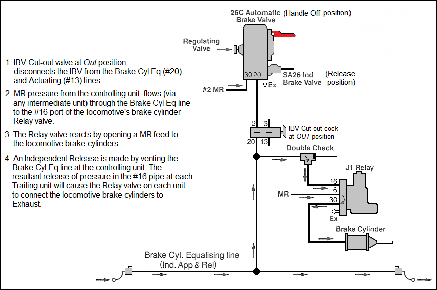
When the engineman desires that an Automatic brake application created at the locomotive is not wanted, it is released by depression of the Independent brake valve handle. This action depresses the internal IBV Quick Release valve, which opens a MR (port 30) feed into pipe #13, the Actuating Pipe. This MR pressure flows in pipe 13 to the Quick Release portion of the Control Valve which functions to interrupt and exhaust the control supply (coming from AR) to the Relay Valve. This then allows the Relay Valve to exhaust brake cylinder pressure.
This process is referred-to as ‘Quick Release’ or ‘Actuation’. Among engine service personnel it is colloquially known as ‘bailing’ or ‘bail-off’.
Locomotive Air Braking Made Easy
The following series of diagrams explain the relationship between the engineer’s Brake Valve and the locomotive Relay and Control Valves.


Air Braking On The train
In its most basic form–still prevalent throughout Australasia–air braking on trailing vehicles is accomplished by the vehicle’s operating valve (Triple- or Control Valve) responding to the reduction in Brake Pipe pressure by connecting the Auxiliary Reservoir to a brake cylinder.
However, where trailing vehicles have multiple brake cylinders or an Empty/Load sensing system is used to vary the trailing vehicle brake cylinder pressure according to load, or Emergency braking functionality is required, a Step-Down Relay Valve will be used. Along with a capable operating valve, this provides for the application of a higher brake cylinder pressure when the car is loaded or when an Emergency Brake Pipe reduction has occurred.
Car brake operation
Some older vehicles may have a basic empty/load function that enables the fulcrum point of the brake rigging to change when bogie suspension becomes compressed as the car is loaded. This changes the leverage off the brake rigging.
More modern cars utilise a relay braking system whereby—during the brake application—the Control Valve supplies Auxiliary Reservoir air to a J-type Relay Valve which—in turn—functions to supply air from a separate source (a Supply Reservoir) to the car brake cylinders.
This system is more capable of handling the large volume provided by multiple brake cylinders, and provides for finer control over the empty/load braking differential. A changeover valve is used that is operated automatically as the car is loaded. This device enables the J-type Relay Valve to supply brake cylinder air at two different pressures – one for when the vehicle is empty and at an increased pressure for when it is loaded.
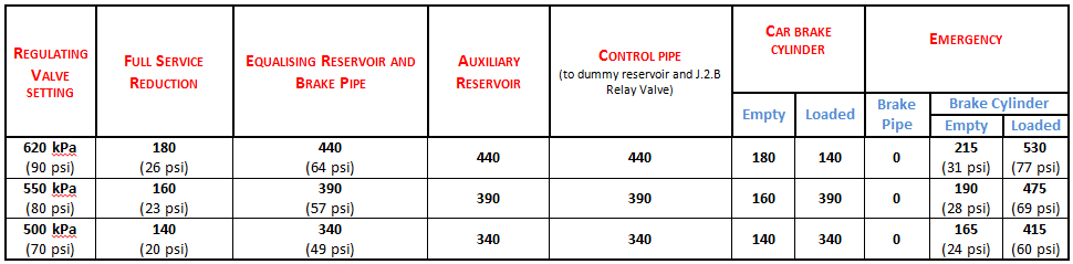
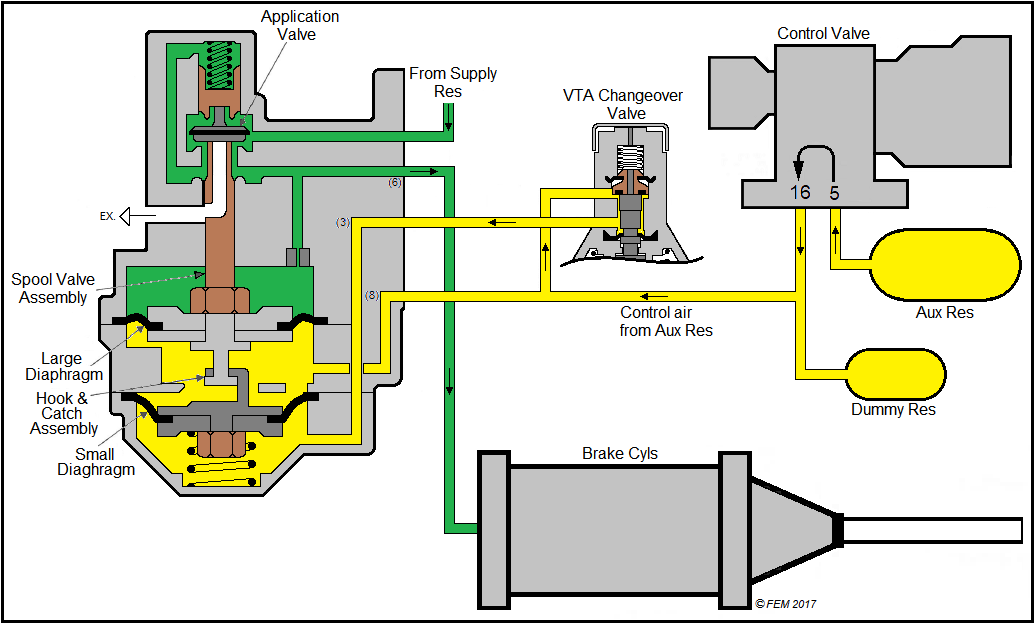
In charging, the Control Valve charges the Auxiliary, Emergency, and Supply Reservoirs to the setting of the Regulating Valve on the locomotive (in this case, 620 kPa). During a Service application, the Control Valve allows Auxiliary Reservoir air to flow to the dummy reservoir. This dummy reservoir is connected to a J.2.B Relay Valve and its volume is equivalent to a car brake cylinder. This simulates ordinary brake cylinder pressure development, and the dummy volume pressure is used to pilot the Relay Valve. The difference in volume between the Auxiliary Reservoir (3,500 in³) and the dummy reservoir (800 in³) means that any amount of air flowing from the Auxiliary Reservoir to the dummy reservoir and the J.2.B Relay Valve has its pressure increased by 2½ times. In a Full-Service brake application this gives approximately 440 kPa in the dummy reservoir and J.2.B Relay Valve. We call this pressure “brake cylinder control air”.
It is interesting to note that since the J.2.B Relay Valve only permits 40% of dummy reservoir (brake cylinder control) pressure to flow to the brake cylinders when the car is empty, then for any given amount of brake pipe reduction (empty train only) the same pressure will apply in the car brake cylinders.
With an Emergency application, an increase of 20% dummy reservoir pressure is achieved, giving approximately 530 kPa. When releasing after a Service application, Emergency Reservoir air—which remains at full pressure during a Service application—flows into the BP to give an accelerated release rate and to assist its recharge.
When releasing after an Emergency application, both Auxiliary Reservoir and brake cylinder air flow to the BP until is within 70 kPa of the BP pressure setting. This helps to achieve a quick, positive release of brakes.
A two-compartment Auxiliary & Emergency Reservoir stores a volume of air to control brake applications. The Auxiliary side of this reservoir has a larger volume then the Emergency side. A Supply reservoir provides air through the J.2.B Relay Valve to the brake cylinders during applications.
An 800 in³ dummy reservoir (equal to brake cylinder volume) accepts Auxiliary Reservoir air during brake applications. It is charged during a brake application, and—because it has a smaller volume than the Auxiliary Reservoir supplying it—has the effect of increasing the pressure of air used to operate the J.2.B Relay Valve such that for any given Service BP reduction, 2½ times that pressure will be impressed upon the J.2.B Relay Valve. It also compensates for disparities in air pressure in car brake cylinders caused by variations in piston travel.
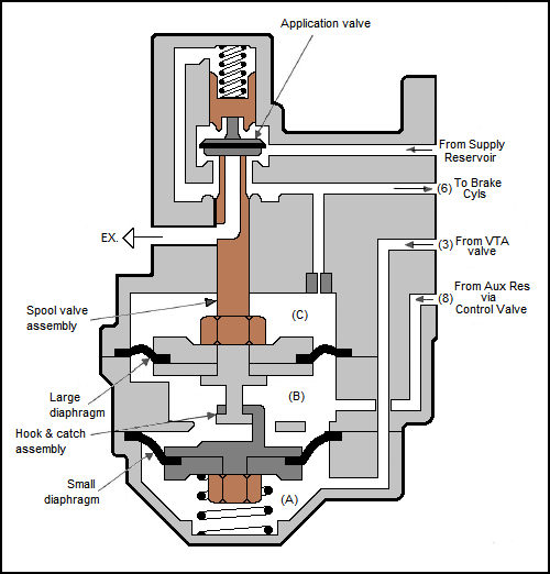
The J.2.B Relay Valve controls the flow of air from the Supply Reservoir to the brake cylinders, maintains against brake cylinder leakage, and provides for release of brake cylinder air. Depending on the flow of air from the VTA (Variable Transfer Application) Changeover Valve, the J.2.B Relay Valve will provide 40% of the pressure of the dummy reservoir to brake cylinders in the ‘empty’ condition or 100% in the ‘loaded’ condition.
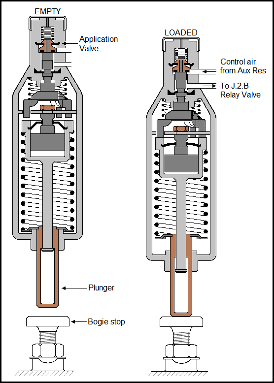
The VTA Changeover Valve operates over a stop on the bogie sideframe, to control—through the Relay Valve–-the proportion of air from the Supply Reservoir to the brake cylinders depending upon whether the vehicle is empty or loaded.
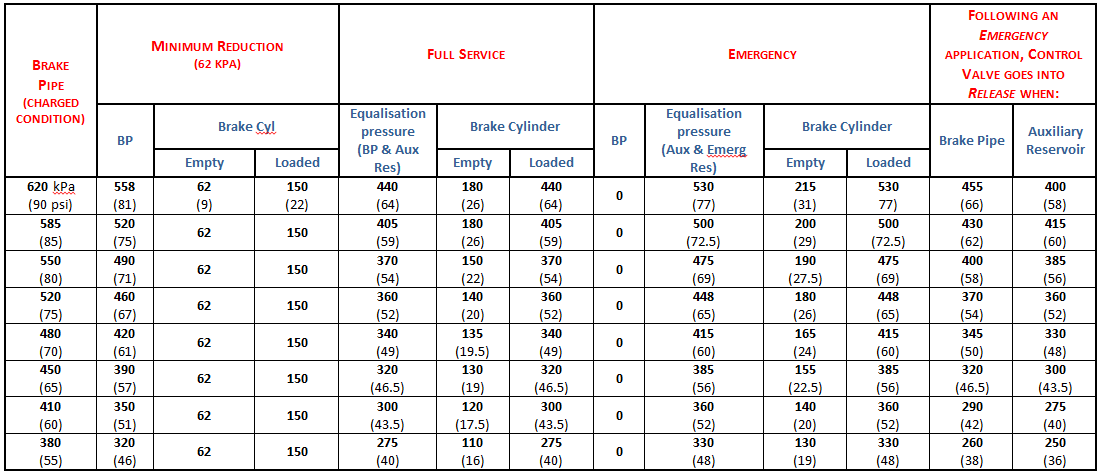
Some comparison tables showing various related system brake pressures