A page for all manner of railway minutiae. After all, the unimportant things deserve to be recorded too!
Official NZR locomotive livery colour chart


An interesting incident… Brazos lift-bridge incident – 1983
‘ROLLINGSTOCK’ – A favourite of mine… is it one word or two? (it’s one of course!)
Rollingstock – Our use of language
FLIGHTS OF FANCY – Loco graphics
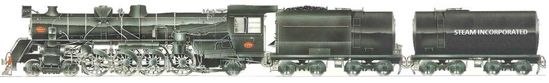
We’ve seen the Norfolk & Western J-Class No. 611 in the U.S. and LNER A3-Class No. 4472 Flying Scotsman in England, running with double tenders… the second being an auxiliary water supply. NZR ‘big-power’ steam locomotives differed from those in that other notable 3′ 6″ gauge network–South Africa–by being constrained in size by a restrictive loading-gauge (mostly the result of colonial-era tunnels) and by the length of turntables. So locomotive boiler size was limited, as was the length of tenders.
What if the main line steam locomotives operated in New Zealand today were run with double tenders instead of the ugly ex-fuel tankers they now tow? The author acknowledges the book, CLASSIC STEAM LOCOMOTIVES OF NEW ZEALAND, Vol I, and tenders abject apologies to its skilled illustrator Eric Heath.
![KA[4]](https://boomerdownunder.com/wp-content/uploads/2018/08/ka4.jpg)
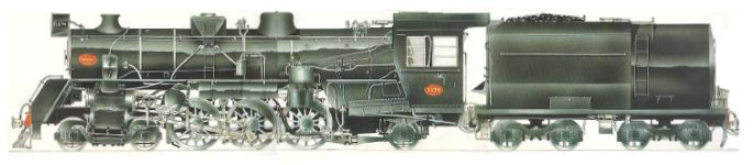
What if the NZGR Ja Class had been a Pacific type? What might they have looked like? Yeah… silly.
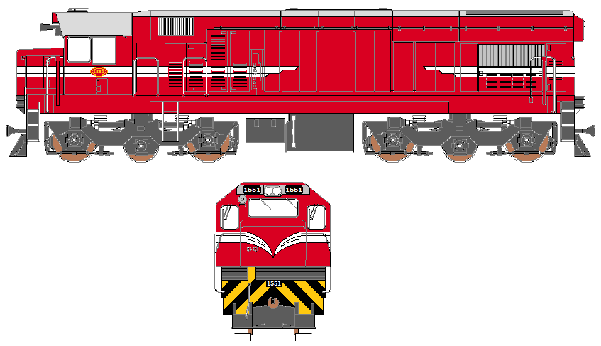
What if the NZR General Electric U26C Dx Class had been painted in the old ‘railcar red’ livery?

What if the NZR rebuilt EMD G12 Da Class (the G22AR Dc Class) had been painted in the old ‘railcar red’ livery?
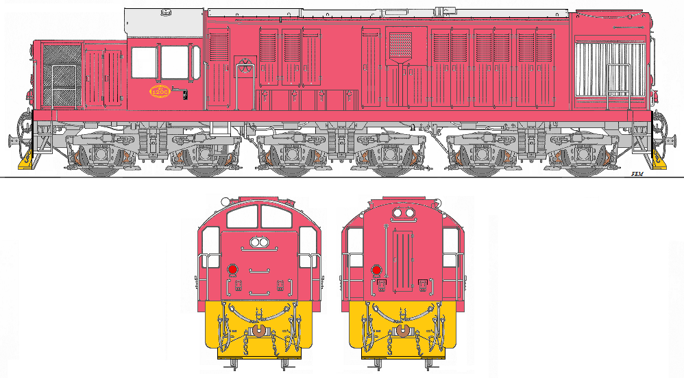
The original ‘Nippon Pink’ Mitsubishi Dj Class livery (with yellow headstocks)
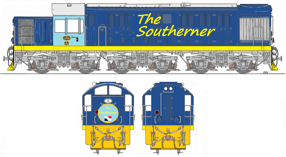
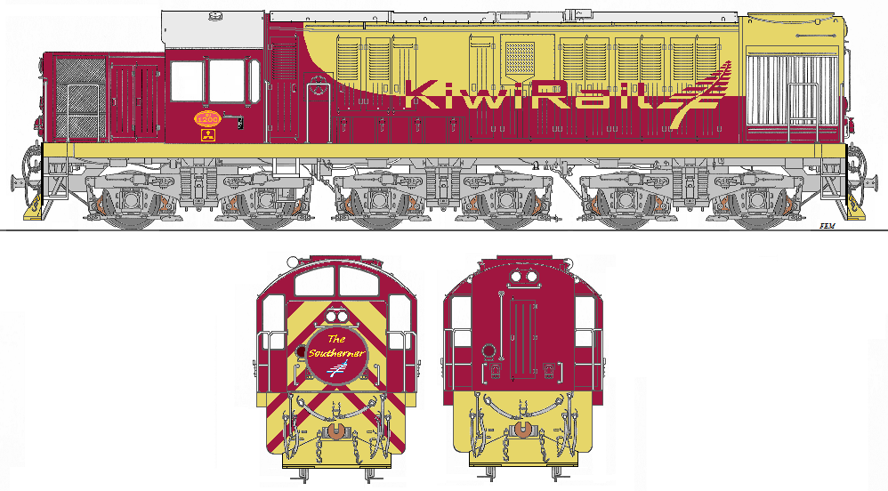
What if NZR had branded the Dj Class locomotives used to haul the Southerner?
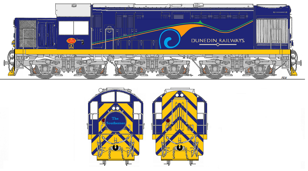
What if tourist operator, Dunedin Railways, chose a matching corporate livery for their ex-NZR Mitsubishi Dj Class locomotives?
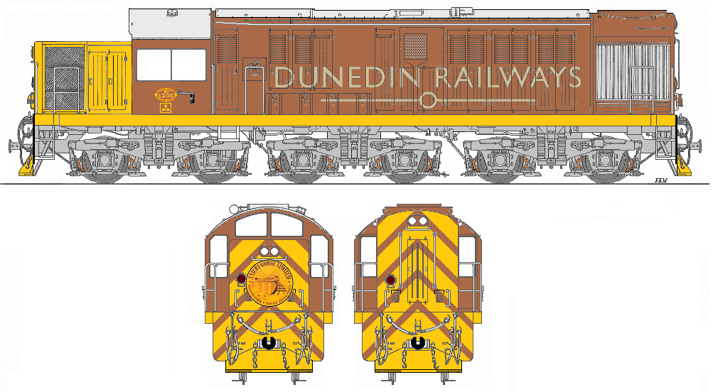
Or this, for the old Taieri Gorge Limited consist?
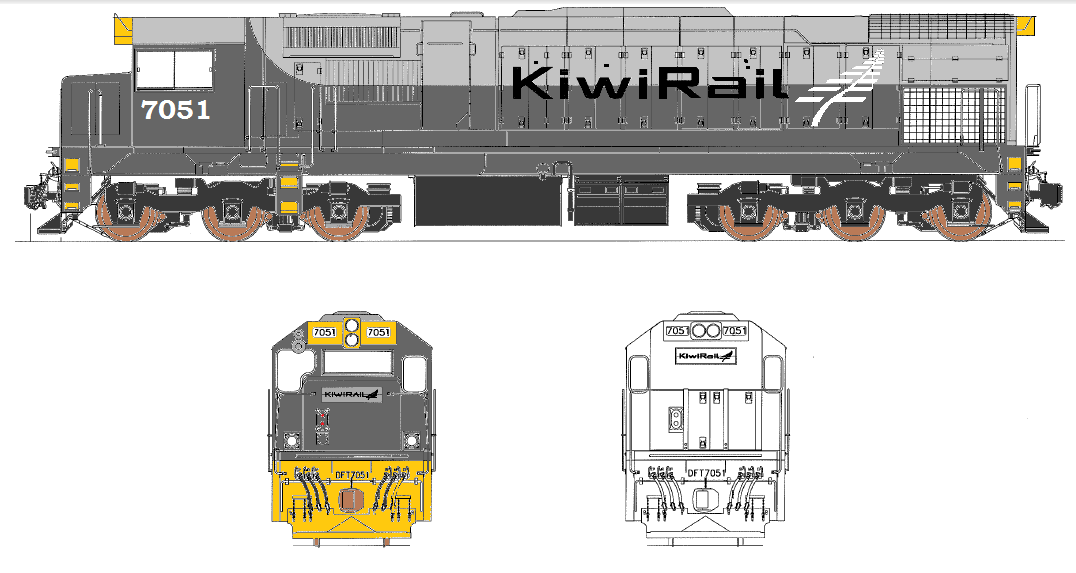
Hey… what about a customised KR livery?
Or maybe a ‘stealth’ livery for the EMD GL22MC Df Class (and derivatives)
Anyways, that’s all quite ridiculous. Enough…!
Steam locomotive restoration (1)
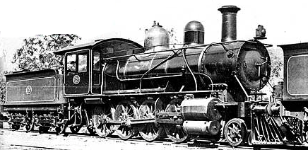
I am pleased to be a financial supporter of the Victorian Steam Locomotive Company who aim to build and operate a Victorian Railways, Vauclain compound-cylinder, ‘V’ Class, 2-8-0. The locomotive is to be numbered V499 after the original class leader, however it is intended to be a representation of the V Class collectively rather than a replica of this particular original Baldwin locomotive. This will allow the VSLC to have the locomotive rendered in up to four different liveries—from Baldwin green to plain black—if they wish to alter it as time goes by.
The VSLC has been inspired by the success of the A1 Steam Locomotive Trust and their famous locomotive, Tornado № 60163. There are also other new-build projects underway in the UK such as BR 4-6-2 Clan Hengist 72010, an LNER G5 0-4-4, LMS 4-6-0 Patriot 45551 The Unknown Warrior, BR 3MT 2-6-2T 82045.
Why is V499 unique?
The V class were the first 2-8-0s on the VR system, and were the forerunner for other 2-8-0 designs to come
They were the only class of 2-8-0s that did not survive into preservation.
They were right-hand drive locomotives on what became a left-hand drive network
They were Vauclain compounds (see https://en.wikipedia.org/wiki/Vauclain_compound)
The class was reported to be very popular with crews, free steaming, and capable of operating everywhere
The locomotive will be the only operating Vauclain compound locomotive in the Southern Hemisphere
The locomotive will be the only Baldwin-designed locomotive running on 5’ 3” Broad-Gauge track
Rather than preserving the 1950s and 60s—as most heritage railways do—V499 will be recreating the 1900s
The locomotive will be a ‘crowd puller’ and a very versatile locomotive for tourist railways
This locomotive will be able to operate on all Broad-Gauge tourist railways due to its light axle loading of 12t 12ctw and short wheelbase
Many V Class and NA Class parts are either identical or very similar. The NA Class locomotives, used now on Puffing Billy trains, were Baldwin-built.
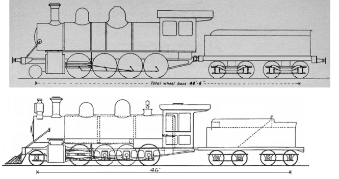
V499 will have the appearance of the original V Class locomotives – in the condition that represents the period 1899-1902. VSLC intend to build an efficient, easy-to-maintain and powerful locomotive that will afford many years of highly capable service. Some examples of its improved features will be: roller bearings on all wheels, higher-grade steel for coupling and connecting rods, original boiler pressure of 200 psi, and a welded tender (with dummy rivets).
The Victorian Railways V Class locomotives—supplied in 1899—were essentially the same model as one built in 1896 by the Baldwin Locomotive Works for the Wellington & Manawatu Railway Company in New Zealand. The New Zealand locomotive—Oc Class No. 16—of course, being on a slightly-smaller scale.
Further details are available at http://www.vicsteam.com/


Steam locomotive restoration (2)
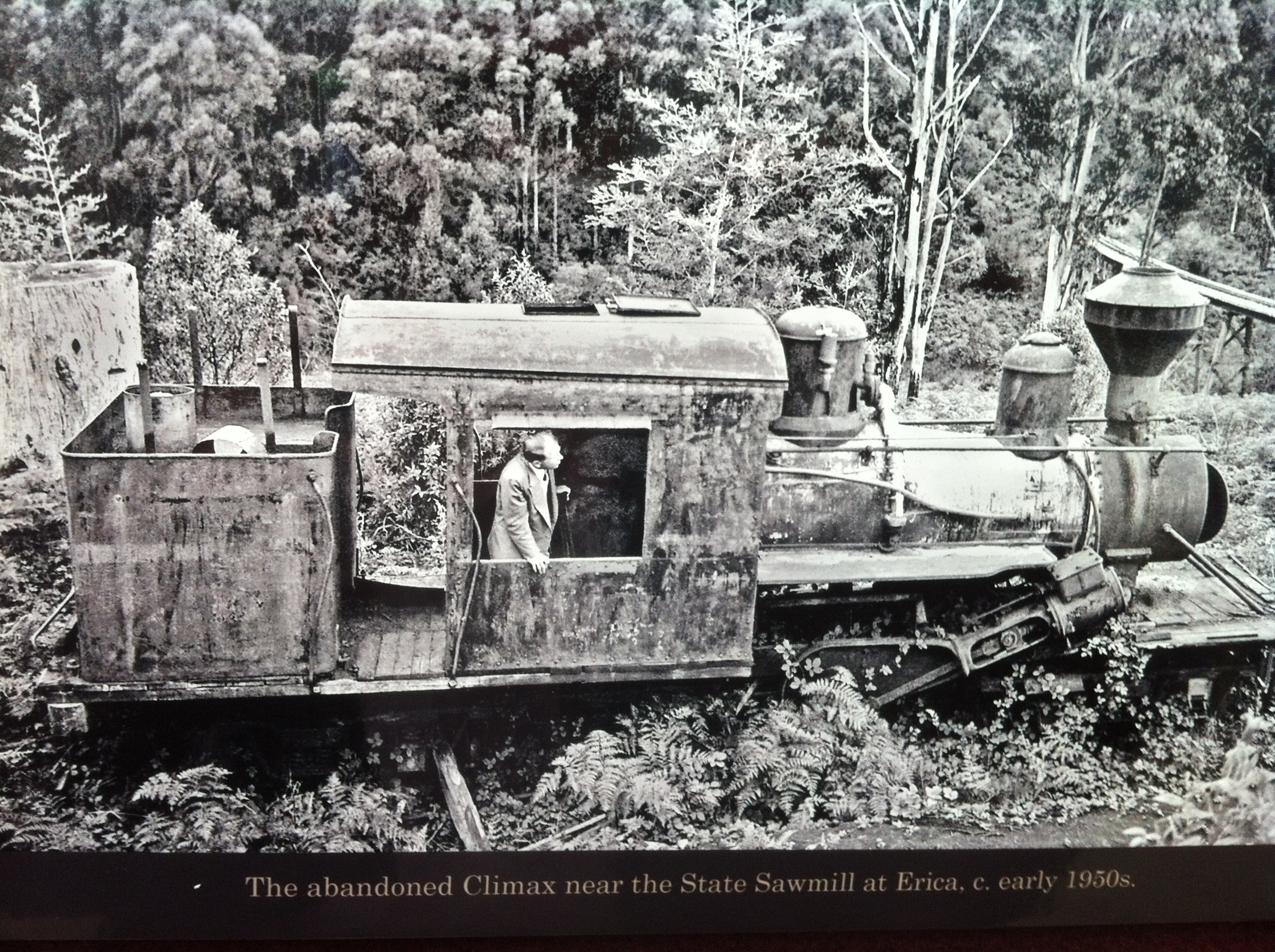
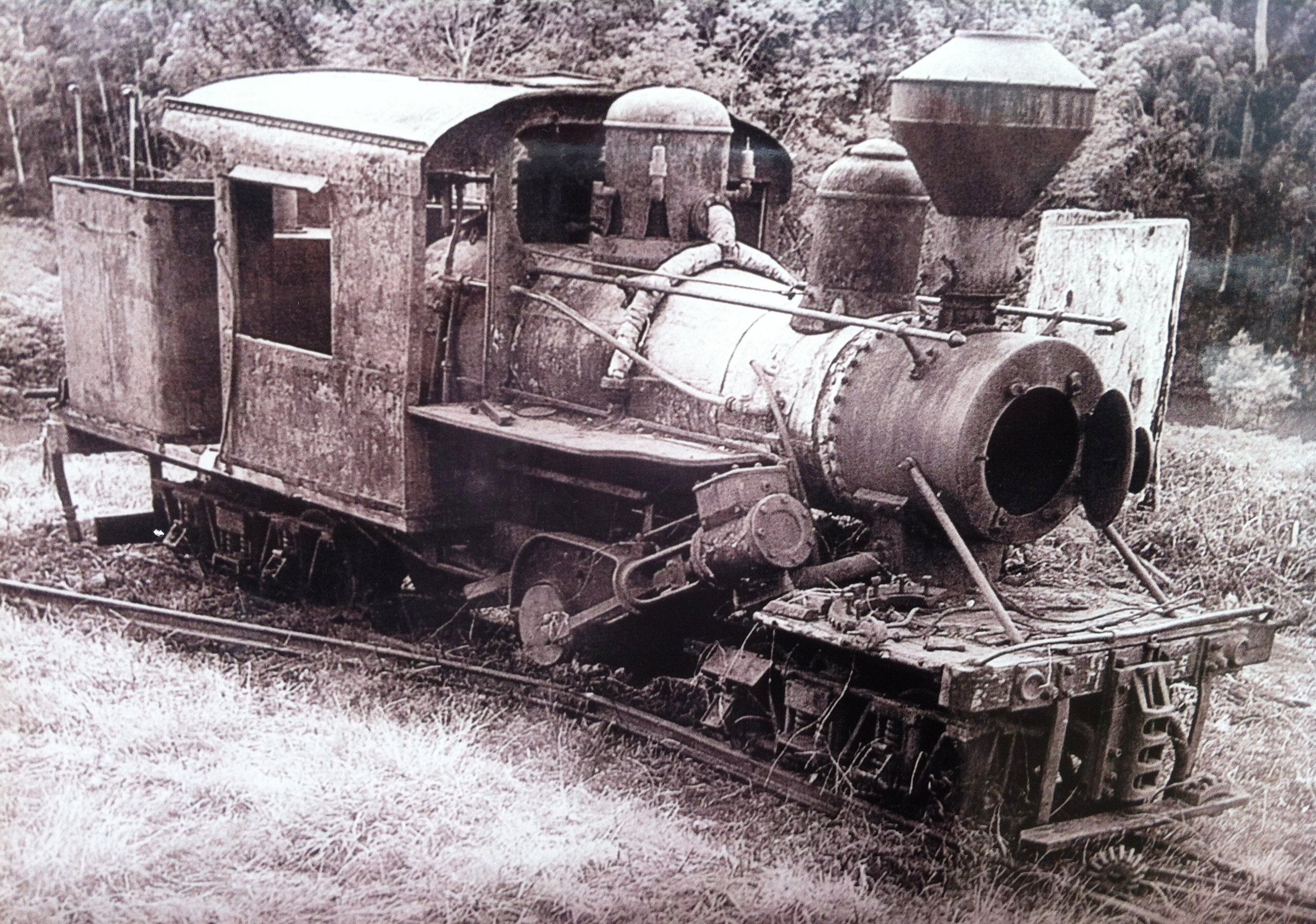
I am also pleased to be a financial supporter of the Puffing Billy Railway Climax Locomotive Restoration appeal to ensure Climax Locomotive No. 1694 is maintained in service. To help achieve this, the Committee has launched the ‘Coffee for the Climax’ appeal – asking donors for the cost of just one cup of coffee per week – AUS$3.50.
Today only about twenty of these locomotives survive; two in Australia, four in New Zealand and the rest in North America. The 1694 has the distinction of carrying the last builders plate of the Climax Manufacturing Company.
The Forestry Commission of Victoria donated the locomotive to the Puffing Billy Preservation Society at the end of its timber industry career. It was initially displayed as a static exhibit at PBR’s Menzies Creek Museum, but was returned to operation in 1988 after 6 years of effort. It was maintained serviceable for the next 13 years and ventured out of the locomotive shed for various special events. Unfortunately, age and use caught up with it and the 1694 was again withdrawn from service in April 2001 for major boiler repairs.
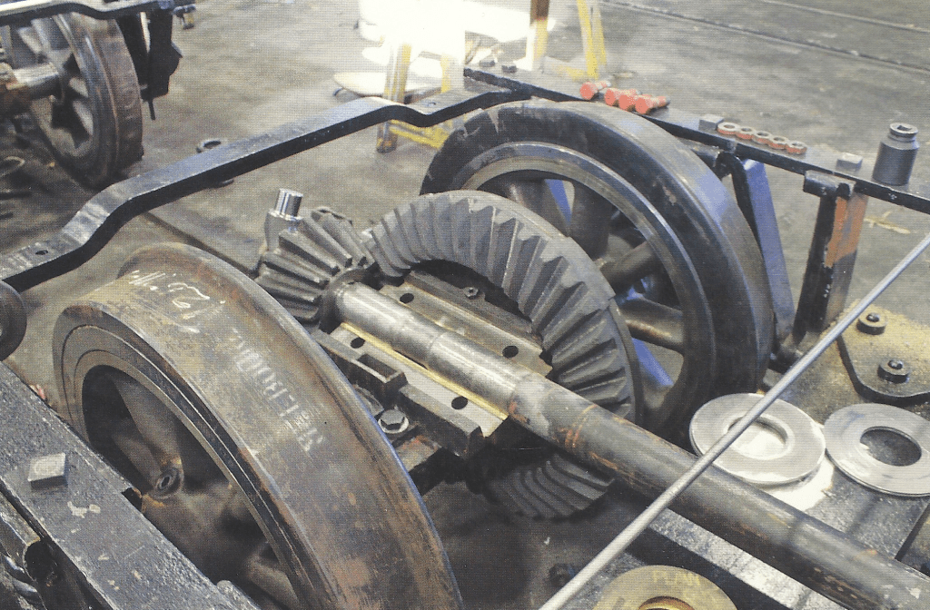
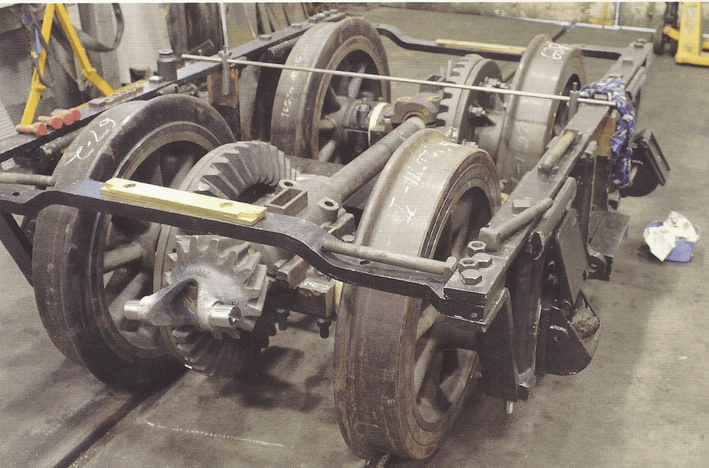
PBR then embarked upon a further overhaul of 1694, with boiler repairs contracted to a restoration firm in the USA. The reward for more than 10 years or effort, fund raising and $700,000 expenditure came on 8 September 2013 when the 1694 hauled its first revenue train since overhaul.
Climax 1694 is not a regular service locomotive at the PBR; instead, being reserved for special operating days and railway enthusiast events. Anyone wishing to see this locomotive in operation should contact the Puffing Billy Railway to ascertain its next planned operating day.
https://en.wikipedia.org/wiki/Climax_locomotive
http://members.ozemail.com.au/~telica/Puffing_Billy_Climax_1694.html


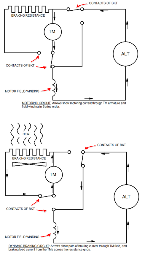
A MYTH ABOUT DYNAMIC BRAKING
I’ve often heard enginemen attempt to explain Dynamic Braking by stating something along the lines of… “Oh, it involves reversing the traction motor connections.” This is not entirely untrue, but it doesn’t really explain anything… and if you prod the person they often can go no further and it begins to sound as if their concept is that the TMs have been ‘reversed’. This confusion probably arises from some very deficient description they’ve read somewhere, and that bad description was probably copied from somewhere else. This is how ‘non-information’ spreads among any group.
Look, here’s a brief summation and a simple diagram to assist. A long time ago, when I had the role of a Locomotive Crew Foreman (otherwise known elsewhere as a Road Foreman or Road Foreman of Engines) I compiled a revised Locomotive and Air Brake Manual for my iron ore railroad (Mt Newman Mining). Regarding DB, I provided this, from my New Zealand Railways instructional material: Dynamic braking is a form of speed retardation obtained by changing the traction motors into generators. The TMs are forced to turn (by the kinetic energy of the train) inside a strong magnetic field which tends to constrain (or inhibit) their armatures from turning, thus setting up a retarding force against the speed of the train. A heavy resistance (the dynamic braking resistor grid) is connected in the circuit to expend the energy generated by converting it to heat which is dissipated (wasted) by a cooling fan (or fans) powered by this energy or by engine-driven blowers (in the case of older generations of diesel-electric locomotives).
When the engineer selects D/B, some high-voltage switches throw to change the TM connections from a ‘Motoring’ to a ‘Dynamic Braking’ circuit. These switches isolate the TM armature from the alternator and connect it across the braking resistance. This results in alternator current being taken by the TM field windings only, rather than by the TM armatures. Being now connected across a resistance, the TM armatures now have an electrical load. In essence, we have created some ‘separately-excited generators’ (i.e. the TMs) with a resistance load.
The level of current supplied through the TM fields determines the level of braking current obtained. The locomotive engineer controls the strength of the TM fields by using (and by varying the position of) the Dynamic Braking Selector Lever. This lever operates a rheostat to vary the degree of alternator excitation, and thus the alternator’s output to the TM field windings.
The amount of braking effort is displayed as TM armature current on the Loadmeter (also known as the Driving Ammeter).
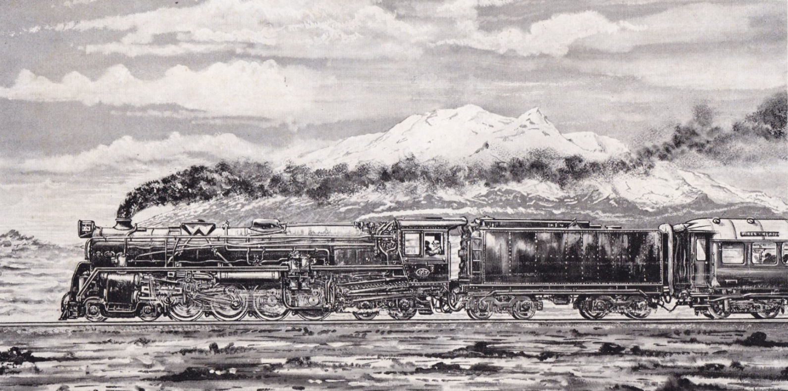
THE MYTH OF HIGH SPEED STEAM LOCOMOTIVE PERFORMANCE IN NEW ZEALAND
I have become interested over the years in the reported speed performance of steam locomotives in New Zealand. It seems that the ‘sources’ used are invariably an unofficial observer with a stop-watch (or, even worse, an ordinary watch with a sweep second hand). And it seems there is never a panel of people from which an average time can be obtained, or official engineering data derived from a dynomometer car or similar valid source.
The problem (or my problem) is that I’m a naturally sceptical person… if something just doesn’t SOUND right or feasible to me, I want to examine it and check it out. And sometimes I just want to say ‘I don’t think so… and here’s why’. Well, I don’t think a JA locomotive can generally run at 70 mph, and here’s why.
The reports we read get published and repeated—not least in sources such as Wikipedia (which page on NZGR JA locomotive performance I have recently sought to update and correct, but am beaten back by the original author who refuses to permit the corrections to be made)—and very soon the whole story acquires pseudo-validity. But the legends are all from people who would LIKE them to be true (such as railfans and locomotivemen) rather than from any provable source. Why do I appear not to accept the stories of locomotivemen as a valid source?
It’s not that I don’t accept them, per se, but that I don’t necessarily accept them. Because consulting a watch from a rushing train over a milepost (or kilometer post) distance, and some friend’s story of driving along a highway actually proves nothing. Then there are the universal limitations of what machinery can do, which NO AMOUNT of myth or legend can alter. One has to acknowledge the constraints, but I’ll get to that later.
To create an official record of speed during a physical event (such as the speed of an object at any given time) we need accurate and incontrovertible evidence of the time that object took to cover a fixed distance. A level of accuracy is critical in—for instance—an Olympic swimming race, where fractions of a second matter. Here, the distance is clearly established and the time is measured by calibrated clocks that are triggered by sensors on the pool starting blocks and within the structure of the pool end-walls. The accuracy of timing at these events is seldom questioned.
It seems though, that those who seek to comment on train speeds—at least in New Zealand—appear to be happy with anecdotal evidence sourced in decidedly un-scientific ways. Locomotive enginemen relish a good war story (and don’t we all?) and, of course, delight in being the subject of one. Their peers, friends, and acquaintances—likewise—feel compelled to provide ‘evidence’ to support or embellish these legends. This is all understandable human behaviour, and the heartfelt intensity conveyed in the earnest protestations of the driver of that express train, that he has seen his speedo needle ‘off the clock’ or pegged at some abnormal or extreme speed, is not to be lightly dismissed nor the tale too publicly questioned. What we see with our own eyes is, oftentimes, all the ‘proof’ we need. Right?
But more than a decade of investigating public transport incidents (I do not usually accept the term ‘accident’) has taught me that although the brain knows what the eye sees, it isn’t always able to process that information to an accurate or precise conclusion. This gives us the phenomenon we describe as ‘perception is reality’. Interested readers might also look up the term ‘cognitive bias’, but that is a ‘human factors’ subject not able to be adequately discussed on this page. Witnesses I interview are often convinced—from what they felt and observed—that something was happening at the time that we know (from other sources) wasn’t. But these people ‘know what they saw’ and they aren’t lying. Except they didn’t actually know what they saw because there were other factors of which they weren’t aware and therefore couldn’t process. They thought they knew what they saw.
So, what might be wrong with the anecdotal evidence so strongly-held in New Zealand about the speed performance of the JA class of 4-8-2 steam locomotive? Well, as the very word (anecdotal) says, it’s ‘hearsay’ and that can render it subjective and circumstantial, and therefore scientifically unreliable. No amount of emotion trumps that. If the locomotive driver said he saw his speedo needle indicating 70 or 75 mph, then he undoubtedly did, and, of course, he wants it to mean that his locomotive was running at 75 mph; there is reputational gravitas at stake. But was he actually travelling at 75 mph? Not necessarily. Unless the instrument had been calibrated to be accurate at that speed and regularly recalibrated (which NZGR steam locomotive speedos were not), then the reading was precisely that… an ‘indication’… nothing more.
Someone on-board the train might thumb a stop-watch as a distance marker flashes by and then again at the next one. How accurate was their stopping and starting of the watch? Could they see the distance marker approaching? How sharply were they poised to press the button? How practised was their hand/eye coordination? How accurately were the distance marker(s) located? Seconds, and fractions of a second, make a difference. Such vital measurements in the Olympic Games are not left to the limits of human ability, and—because ‘demonstrated accuracy’ in the field of locomotive speed measurement for the record is just as crucial—it needs to be conducted with a similar measure of vigour and resolution; and I’m not aware that it ever has been.
A car driver might report that he was traveling at 70 mph and the speeding steam locomotive overtook him. But was that car driver really traveling at 70 mph? How could they be sure of that? Were they travelling at 70 mph constantly for an extended distance? Probaby not – it was a public highway, after all. There was other traffic, there were intersections, and villages, and highway patrols. But the steam locomotive probably was running at a pretty constant speed. Not unlikely, then—under such circumstances—for the train to appear to be pulling away.
Written reports can frequently be seen that serve to perpetuate the myth. This rather colloquial Wikipedia account (with my additions and emphasis) is typical. “The loco[motive] excelled when hauling the South Island Limited [Express] between Invercargill and Christchurch, notably on the fairly flat Invercargill-Dunedin section and particularly on the fast run across the Canterbury Plains between Christchurch and Oamaru, and the evening run back on 144 to Christchurch was legendary [reference to a statement made in someone’s DVD production] on occasions when the train was late and racing to get to the Lyttelton-Wellington Ferry [Union Steamship Company ‘Steamer Express’] prior to its sailing. The maximum official speed was 100 kilometres per hour (62 mph) [it wasn’t, by the way… it was 55 mph], but the class operated effortlessly at higher speeds, especially across the Canterbury Plains. Ja 1267 pulling ten carriages weighing 300 tons covered the 42 miles (68 km) from Tinwald to Washdyke at 59.4 miles per hour (95.6 km/h).[again, a reference to an anecdotal statement made in someone’s book. Where is the provenance?]
The report continues; “Reliable [a judgement made by whom?] footplate observers of the Ja [class] on the South Island Limited during the late 1960s saw the speedometer over 75 miles per hour (121 km/h) and the train moving away rapidly from the traffic on State Highway 1, adjacent to the railway. [again… repeating an anecdotal statement made in some railfan’s book]
Traffic into Christchurch over the Plains [sic] on state highway [sic] One [sic] on [sic] late 1960s, evening [sic] usually ran over the speed limit at 65 mph plus [sic. Again, where is the provenance? The passage reads as if copied and pasted from that railfan’s book]. Rail writer David Leitch, a Masterton lawyer [at the time], believed Ja [class] drivers’ accounts of 85 miles per hour (137 km/h) running as [being] accurate. [This repeats a breathtakingly-ludicrous anecdotal statement made by the late Mr Leitch in his book. How much damage to factual history has been created by foolish nonsense such as this?]
The account lumbers on; “Additional support [?] comes from an official source, the 1966 Encyclopaedia of New Zealand, [in] which [somebody – we don’t know who] states ‘The speedy and graceful “Ja” has demonstrated its remarkable performance in express service on the level plains of Canterbury, and on occasions has attained speeds in excess of 70 miles an hour.’ [again, that reference to an anecdotal statement made in someone’s book or amateur video presentation]
The official NZR speed record of 125.5 kilometres per hour (78.0 mph) was set by a Vulcan RM class railcar on a delivery trial run in 1940 (see the Encyclopaedia of NZ reference above), but the Ja class unofficially [my emphasis] operated at higher speeds [?].”
Notice how easy it is to just state these things? As any good politician knows, if you say or print something enough times, the mug voter is liable to come to ‘believe it’. While the above-mentioned accounts are attributed to people who are described as ‘reliable footplate observers’ (assumed either to be either locomotive enginemen or excited lineside and on-train observers… and in the case of Mr Leitch, a railfan who had set out to obtain footplate experiences which readers are—it appears—expected to assume makes him some sort of an authority), anonymous ‘unofficial’ sources, and—in one case—to an ‘Encyclopaedia’, it should be remembered that they are all anecdotal. There is simply no known published scientific data on any speed trial of any locomotive of the modern J classes. There is also no acknowledgement of the dubious provenance of data acquired—in a non-scientific form—from such non-precision sources as vehicle and locomotive speedometers, or from the human hand manipulating a stop-watch while the human eye judged the relative position of a distance marker as the train passed that marker at speed.
I have sought—at times—to question the stories related by locomotivemen about the legendary capacity of the JA class for speed. This is never done lightly, as locomotive enginemen who have had a career on steam motive power are held in high esteem—even venerated—within both the railfan and locomotive engine service communities (and so they should be… to a degree). Due to the assumed quantum of their experience, their accounts and recollections are accorded almost universal deference as ultimate sources of knowledge. Most certainly, this dwindling band of old warriors (and this writer considers himself to be only slightly less ‘old’ than some of them) deserves respect and to be acknowledged for the lifestyle they endured, the challenges they faced, and the learning they accumulated. But they are not Gods, and their accounts of exploits and their opinions on matters technical need to be treated with the same caution you would reserve for anybody expressing an opinion.
A working life safely operating the controls of steam locomotives and piloting those locomotives across various safeworking environments is testament to accrued expertise on driving and firing. It is not necessarily proof that each of these enginemen was a technical expert. My own experience has taught me that while there are very many ‘old’ enginemen who were greatly experienced, had great levels of expertise, and were—more often that not—all-round nice people, those factors did not automatically make them experts in everything about steam locomotives. Even less, does this apply to the current crop of younger members who are fortunate enough to be able to operate these historic machines (and because of whose enthusiasm and participation, which I freely acknowledge, we should all consider ourselves to be fortunate).
What CAN be proven, though, is that on a locomotive having a 54-inch diameter driving wheel and a 26-inch piston stroke, traveling at (let’s say) 65 mph, the driving wheel will be revolving at 405 rpm and–since each piston completes two strokes (one forward and one backward) per revolution of the driving wheels, those pistons will be reciprocating at 6.74 x 2 =13.48 strokes per second. These are not complex calculations. Raise the speed to 70 mph and the figures become 435 rpm and 14.52 strokes per second. These figures for driving wheel rpm may seem low by comparison to a modern internal combustion crankshaft, but they refer to what are really 54-inch flywheels, and—make no mistake—these are rapid revolutions.
Think then of the piston speed. Steam locomotives require the valves in the steam chest (which are driven from the driving wheels at a rate of reciprocation that relates to driving wheel speed) to be admitting and exhausting steam effectively-enough to maintain speed or to accelerate. At 65 mph and 13.48 piston strokes per second, one can imagine the infinitesimal time periods that are available for those critical valve events—admission, expansion, compression, and exhaust—to occur for each stroke. On this basis alone, the question must arise as to how much faster could these pistons possibly move and still be able to receive, use, and exhaust a meaningful supply of steam. Could they move at 14.52 strokes per second and the valve events still enable the locomotive to propel itself? Were the locomotive’s steam passages designed for optimum fluid flow? How much faster could the valves (which are also pistons) move and still be able—with cut-off hooked right back—to provide an effective time-period for supply and exhaust of steam? There must be limits, and I think there are. I’ll get to that.
A comparison can be gained from the record-setting British A4 locomotive № 4468, known as Mallard. At the claimed record speed of 126 mph, its 80-inch driving wheels would have been revolving at around 529 rpm and its 26-inch-stroke pistons reciprocating at 17.64 strokes per second. All of this was extremely rapid. Why could the JA not do the same? Well, [1] because this was on standard-gauge track maintained to a standard (and possibly even specially-prepared for this speed trial) not common in New Zealand, [2] Mallard is a 4-6-2 that benefitted from the superb balancing provided by three cylinders and various advanced steam- and gas-flow improvements (the latter being features with which no NZGR locomotive was ever designed), [3] the posted top speed was achieved on a downgrade of between 1:178 and 1:200, and [4] that maximum speed was verified by a dynamometer car (and was only attained for an instant before it dropped back). There can be no credible comparison with the performance expected (or the mechanical capabilities) of a NZR JA even at the oft-mentioned 70 mph. And the claims become even more incredible when some commentators write—with disproportionate zeal—of JAs at 85 mph!
Even at a theoretical 80 mph, our little JA driving wheel would be revolving at just under 500 rpm and its pistons reciprocating at 16.58 strokes per second! What physical chance, with the engine rocking along on New Zealand Government Railways’ modest track standards and pounding across numerous non-interlocked siding turnouts that this could have ever really occurred? And let’s not forget that back in the day, there was also the tablet to be picked up (at a maximum permissible speed of 40 mph) at stations that, in some cases, might only be 10 miles apart. Later working under CTC signalling hardly changes any of that. We should be cognisant too, that although those hardy engine-souls are sitting up there in a cab that is around 8 feet wide, the pounding wheels below them are only 3-and-a-half feet apart! Something known as ‘stability’ comes to mind.
Earlier in this treatise, I spoke of the limits of machinery. This term is intended to refer to a physical state (or states) beyond which a composite object; in this case a manufactured movable assembly of components—themselves moving to their own laws of physics—(in other words, a ‘machine’) cannot proceed lest the machine be forced to destruction. The subject falls within what is known as ‘classical mechanics’. I’m not a professional engineer and thus not qualified to expound in detail on the Laws of Isaac Newton and the complex interactions between the various pertinent phenomena involved here, such as force, mass, acceleration, velocity, momentum and kinetics. So I don’t know what those limits might be for any steam locomotive, but our imagination might be able to help us remain in touch with reality. The motion and drive rods have a lot to do… and they can only go so fast in doing it!
Whatever it’s reciprocating speed, a piston has to change direction at each end of its stroke, and that means it has to STOP at each end of its stroke… however momentarily. So does the piston valve, which is being driven from this drive train via the valve motion, except that the valve is also subject to the influencing factors of Lap and Lead; one being a fixed setting in the valve motion, the other through variable adjustment available to the engineman. The piston stroke is transmitted to the connecting rod. At one end (the crosshead), that conrod must also stop at the end of each stroke—along with the piston–while the other end does not. That ‘other’ end—and the attached siderods—are fixed to the wheel (assuming a two-cylinder locomotive) at a distance from the centre of the axle that equates to half the length of the stroke. So, from front (or back) dead-centre—assuming the locomotive to be moving forward and the observer to be looking from a side-on elevation—to the other horizontal dead-centre (back or front respectively), the rods move lengthwise (in horizontal plane) by a distance equal to the piston stroke. Between these points, the rods move vertically (up-and-down in the horizontal plane). From front dead-centre the movement is down through the bottom quarter then up (via back dead-centre) to the top quarter, then down to return to front dead-centre. So, the rods ascribe an orbital rotation around the wheel (or do they rotate around their crankpins? Or do the crankpins rotate around the wheel? I confess I’m not sure how it should be stated). Either way, maximum available thrust is exerted only—and for a finite period of time—while the rods are moving between their front and back dead-centres (termed ‘dead’, because positive piston pressure in these positions can cause no rotative impulse). Continuity of thrust—of course—is maintained by one ‘side’ of the locomotive being offset from the other, which is why a locomotive being operated on ‘one side’ only, must not be stopped with that side on either front or back dead-centre, lest it cannot then be moved. It also explains why two-cylinder steam locomotives have such a pronounced ‘yaw’ motion, as the thrust is exerted upon the frame alternately from one side then the other.
The point of this description of the operation of running gear is to illustrate how the ability of a steam locomotive—as a machine—to move, is physically reliant upon a series of mechanical laws. The abilities of the machine to accelerate to infinity probably exist in theory, but in reality, destruction can be expected to intervene. A locomotive… any locomotive… can only go SO fast. For a NZGR JA class steam locomotive, 65 mph is pretty fast and has to be close to its physical limit!
This rebuttal is not to diminish the stature and reputation of the steam enginemen who ran those locomotives. But these men don’t need to be accorded godly status, and they probably wouldn’t accept it anyway. Conventional wisdom tends to demand that the commentator who has not had a lifetime on the steam footplate (or perhaps has less experience than someone else) is, therefore, not entitled to the right to a published opinion that differs from those who have. But even a lifetime on-board steam locomotives did not necessarily equip these men with an accurate, verifiable knowledge of what speed their steeds really attained at their limit. Anyone who’s ridden the deck at speed knows what ‘fast’ feels like. Perception, though, is NOT always reality.
When we discuss the speed performance of the JA class of NZGR steam locomotives, it would be desirable to retain a sense of reality. I think we can acknowledge the performance of these thoroughbred locomotives while remaining grounded, although it is a great pity that so many written (and sometimes spoken) sources across our connected world continue to display this factual misrepresentation.

REGARDING COMPRESSOR OPERATION ON GE DASH 8 & 9 LOCOMOTIVES – Pumping air
Modern microprocessor-controlled GE locomotives may have one of these placards fixed to the control stand:

Alternatively, a locomotive with a non-GE standard cab layout may have an instruction in its Operator’s Manual. For example, the engineer’s Operating Manual for NR Class locomotives (a GE Dash 9 model built under licence in Australia) states, with regard to throttle handle position, The most economical air compressor pumping position is: Reverser in Neutral, throttle in N.1, with GF switch off.
All of these are somewhat misleading instructions as it is not made clear just what is meant by “optimum air pumping”, “optimum train charging”, or “most economical air compressor pumping position”.
In most instances, these locomotives operate at their ‘optimum’ anyway—including with regard to pumping air—and need little assistance from the engineer in this regard. The WABCO 3CMDCBL and 3CDCLA air-cooled compressor as installed in Dash 8 and Dash 9 locomotives built in Australia delivers between 218 cfm of air in IDLE and 236 cfm in Notch 8. By comparison, the 3CWDL water-cooled compressor fitted to most Pilbara ALCO C636 locomotives, delivered between 123 cfm (IDLE) and 338 cfm (N8).
It is obvious that in the lower engine speeds, at which you would be pumping air when stationary (charging the Brake Pipe), the Dash 8 and 9 locomotives have a superior compressor delivery rate. It is important though, to be aware that it’s not the compressor that charges the BP – it’s the Main Reservoir! Not all locomotive drivers consider this. Some will unnecessarily increase the engine speed to charge their train even though the MR pressure is being comfortably maintained by the compressor with the engine at a lower speed, or even at IDLE! The notion that you can shove the air back down the Brake Pipe faster by running the diesel engine faster is a fiction, and if the Main reservoir is fully-charged it is futile.
Remember, the compressor does not charge the BP. The compressor charges the MR and the MR charges the BP. If the MR pressure is within range (i.e. the compressor has unloaded or stopped), then making the compressor run faster is a waste of time and fuel. So what do the above instructions really mean?
But hold the phone a minute!
Do you remember learning about the three main components of the Dash 8 (and -9) Electronic Control System? These are the CAB, EXC, and AUX controllers (plus IFC and EFI on Dash 9s). A full description of these belongs to another day (but you can look it up yourself). However…
To understand the compressor operation and the ‘train charging’ placarded instructions, we have to understand how the EXC controller on Dash 8 and 9 locomotives is programmed to command engine speeds and compressor operation. The compressor on these modern locomotives is not coupled to the engine crankshaft, therefore increasing the engine speed will not necessarily increase the compressor speed.
The Dash 8 and Dash 9 locomotive compressors are run by their own ac Compressor Drive Motors (CDM’s) which have dual field windings – one set for 6-pole operation (whereby the CDM runs at twice engine speed), and the other for 12-pole operation (whereby the CDM runs at engine speed). At LOW IDLE, IDLE and NOTCH 1 engine speeds, the CDM runs in 6-pole operation and for HIGH IDLE (if fitted) and Notches 2 to 8 inclusive it runs in 12-pole operation. Again, this is commanded by EXC controller.
A quick note about GE engine speed schedules…
Current-model GE locomotives share the same basic engine speed schedule, often with some minor software differences. With the Robe River and BHP Iron Ore Dash 8 units, four throttle positions (Notches 3-6) have the same rpm and because this is Notch 6 speed, GE call this the ‘Quad 6’ engine speed schedule. By comparison, on the Hamersley Iron and National Rail Corp (now called Pacific National) Dash 9 units, engine rpm remains unchanged through just three consecutive throttle positions (Notches 4-6)—also being Notch 6 speed—and this is GE’s ‘Triple 6’ engine speed schedule.
Let’s look at this engine speed schedule (Note that for the Dash 9’s, Notch 3 speed is the same as Notch 2):

From the above generic engine speed schedule and the previous information on the operation of the Compressor Drive Motor, it can be seen that with the throttle handle in IDLE, the compressor—when running—will be controlled at around 888 rpm (or thereabouts), equivalent to Notch 3-6 or 4-6 engine speed. This happens anyway, without the assistance of the driver so why the instruction to place the throttle handle to N.1. for optimum train charging? Well, here’s why…
In certain circumstances (e.g. [1] engine cooling water temperature above 72 degC, [2] battery charging voltage within range, and [3] Reverser in NEUTRAL), EXC controller will send the engine to a fuel-saving LOW IDLE (using about 17.8 lb/hr of fuel). Looking at the engine speed schedule, we see that when this happens, the compressor—which is running at twice engine speed—would be at 682 rpm (2 x 341) rather than 882 rpm.
However, should the throttle handle be at N.1 position per the above instruction (plus GF switch OFF and Reverser in NEUTRAL), engine speed is at 441 rpm (with fuel usage increasing to around 25.8 lb/hr) and compressor speed at 882 rpm, but EXC controller is prevented (or ‘locked out’) from reducing it to LOW IDLE. This is desirable and ensures that the compressor is made to operate at its fastest possible speed consistent with the lowest practicable engine speed (therefore saving fuel).
Summary:
Engine speed at IDLE is the same as N.1 anyway. The engine may go to LOW IDLE (a computer-controlled fuel-saving feature) unless it’s ‘locked out’ from doing so by having the handle in N.1 position. This is the reason for the instruction, which is advisory only. As long as Main Reservoir pressure is within range, there’s no reason to lock out LOW IDLE and thus prevent an 8 lb/hr fuel saving!
You may need to read this twice, and I wouldn’t blame you.
OH NO… HERE’S MORE STUFF ON THE GENERAL ELECTRIC Dash 8 LOCOMOTIVE
In case you haven’t read enough arcane Dash 8 stuff…
In 1988, the first of the new Goninan-GE Dash 8 locomotives were about to arrive at Mount Newman Mining. I was a locomotive crew foreman at the time and was invited to attend a technical training school being presented to locomotive workshops staff by GE personnel. These worthy individuals had magnanimously agreed to allow their company to send them from the frozen winter shores of Lake Erie…
…to the balmy climes of tropical Port Hedland. One of them was Mike A. Dombrowski, a design engineer with GE Transportation Systems, who—through his easily-interpreted ‘cartoon’ diagrams—had a great way of imparting technical systems knowledge. If you’re interested in Dash 8 locomotive systems, perhaps how the Traction Alternator is used to crank the engine, or just the comparisons between the late-model Dash 7 and the (then) new Dash 8, click on the link and immerse yourself… (and forgive me for my scribbled notes).
